
CMS Overview
Cisco Meeting Server (CMS) brings audio, video, and web communication together in a single on-premise conferencing solution. The platform is scalable and interoperates with a variety of 3rd party solutions.
The CMS software, regardless of the hardware platform, comes bundled with all necessary components to deploy every feature. It is up to the administrator to configure one or more CMS service components to provide scalability, redundancy, and functionality such as external access. The CMS software is available for dedicated hardware appliances as well as a virtual appliance.
Deployment Models
There are three deployment models for CMS: Single Combined, Single Split, and Scalable and Resilient Meeting Server deployments. The Single Combined deployment model is exactly that - one server running all the services you need. In most cases, this type of deployment is applicable only to internal-only access and in smaller environments, where the scalability and redundancy limitations of a single server are not a critical concern, or in situations where the CMS is only tasked with specific features, such as ad-hoc conferencing.
The Single Split deployment model extends the previous configuration by adding a separate server for external access. In legacy deployments, this meant deploying a CMS server in the edge network, where external clients could reach it, and one CMS server in the core, where internal clients have access. This particular deployment model is now being supplanted by what is called the Single Edge, which consists of Cisco Expressway servers, which either have or will have many of the edge traversal capabilities, so customers will not need to add a dedicated CMS edge server just for CMS.
This leads us to the final deployment model: Scalable and Resilient. This includes redundancy for each component, allowing for the system to grow with your needs to its maximum capacity, while providing redundancy in case of failure. It also leverages the Single Edge concept to provide secure external access. This is the model we will examine in this lab. If you understand this, you will not only understand the other deployment models, but it will allow you to understand how to build a system with growth in mind.
The newer single edge architecture, which you will deploy in this lab, still includes all core roles for CMS, however we will utilize the Cisco Expressway series of products to allow external access to our meetings and provide secure firewall traversal. While there are currently still some feature gaps between the single edge model and the traditional Acano/CMS deployments, we will introduce the concepts for deploying a Collaboration Edge that can be applied regardless of CMS or Expressway.
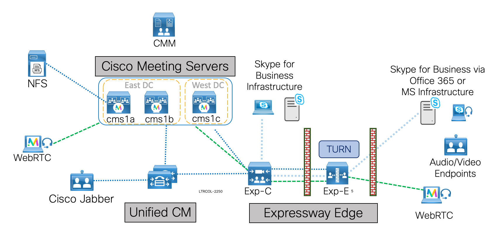
Lab Topology
The lab topology presented here will expose you to configuration methods and design concerns applicable to every complex CMS deployment.
Software Components
The core software components for CMS are:
- Database: Allows some configuration, such as dial plan, spaces, and users to be aggregated. Supports clustering for high availability only (single master).
- Call Bridge: The audio and video conferencing bridge, including all call control and media processing. Supports clustering for high availability and scalability.
- Web Bridge: Provides access for WebRTC clients
- Web Admin: Administration GUI and API access, including for Unified CM ad-hoc conferencing
- Recording & Streaming: Call recording and streaming functionality
You will note that we did not include things like Loadbalancer or TURN server. These are CMS components that are deployed exclusively in the edge network. For this lab, we will not deploy any CMS servers at all in the DMZ at the Edge. We will leave this functionality for Expressway. This does currently limit us to not being able to deploy CMA (other than WebRTC CMA), however this can leverage an existing Expressway deployment and traditional CMA will eventually be supported by this architecture.
For this lab, we will examine the scalable, resilient deployment model for CMS. We will add call control via the Unified CM and provide external access with the Cisco Expressway as well as management capabilities with Cisco Meeting Management (CMM). In understanding these components and the interactions between the products and their features, we will better understand how CMS is deployed in nearly every other deployment scenario.
The software versions used in this lab are CMS 2.9, CMM 2.8.0.97, Expressway X12.5.6 for external access, and Jabber 12.7.1 as our video client. Differences in product capabilities or configuration steps may exist in older or newer versions.
Configuration Modes
Unlike most other Cisco products, Cisco Meeting Server supports (in fact in most cases requires) three methods of configuration to get any larger deployment off the ground:
- Command Line (CLI): The command-line interface, known as the MMP (or Mainboard Management Processor, from the Acano appliance days), for initial configuration tasks and certificates.
- Web Admin: Primarily for CallBridge-related configuration, especially when configuring a single, non-clustered server.
- REST API: Used for most advanced configuration tasks and those that involve a clustered database.
In addition, the SFTP protocol is used to transfer files - typically licenses, certificates, or logs - to and from the CMS server. While there may be tools that can configure much of this, it is imperative for administrators to understand and be comfortable with each of these methods of access and the type of information each provides.
Before getting started, let’s map out exactly what you will accomplish in this lab:
- Basic CMS Server configuration: The IP addresses and basic services such as NTP, DNS, and some certificates have already been configured for you. You will want to be sure that everything is set up properly before going any further. These services are crucial with any deployment because DNS lookup failures or inaccurate clocks can lead to issues that can be challenging to troubleshoot during the setup process.
- Configure CMS Database Clustering
- Configure the WebAdmin component
- Configure the CallBridge component and CallBridge clustering
- Configure Web Bridge
- Configure LDAP Synchronization and Authentication on CMS
- Configure a CMS Inbound and Outbound Dial Plan
- CMS call control integration via Cisco Expressway and Unified CM with load balancing considerations
- Optional bonus section - Advanced features, such as Space creation, Ad-hoc conferencing, and Branding
- Optional bonus section - Set up Expressway Edge: Web Proxy for WebRTC and TURN server
- Optional bonus section - Integration with external Skype for Business via Expressway
- Optional bonus section - Integration with on-premises Skype for Business
- Optional bonus section - Administering CMS meetings with Cisco Meeting Management
In this lab you will use the Secure Shell extension for Google Chrome for MMP (SSH CLI) access. For Web Admin access you will use Google Chrome, and for API-related configuration tasks we will use the Postman application.
Throughout this lab, you will find that CMS is indeed a powerful product with many features. It is truly a Swiss Army knife for interoperability. While it is impossible to cover all scenarios, we have tried to highlight a few specific configuration methods and design practices that will help you understand the CMS capabilities as well as give you the tools to deploy these or other features successfully.
Configuring Call Bridge
Now that the underlying database and the REST API are available by enabling Web Admin, you can focus on enabling and configuring the most important of the core services, the Call Bridge. You will also license your CMS servers in this section as well. The Call Bridge is the one service present in every CMS deployment. The Call Bridge is the main conferencing engine. It also provides the SIP interface, so that calls can be routed to/from it from external call control, such as the Cisco Unified CM.
|
Enabling Call Bridge
As with other services, initial configuration of the Call Bridge begins in the CLI. And as before, you must assign certificates for the service and bind the service to an interface. Start by connecting to server CMS1A.
| Cisco Meeting Server Name | Password |
|---|---|
Enter the following command to associate the certificates with the Call Bridge service:
Next bind the service to an interface:
Finally, restart the service:
The callbridge command gives some status information about the Call Bridge service, although it is primarily to check that the certificates are assigned.
CMS1b and CMS1c already have their certificates installed, so no need to do anything to those servers.
Install CMS Licenses
Now that the Call Bridge service is enabled, you can install the licenses. You may be wondering why you didn't install the licenses earlier. There is an issue where if you install the license before the Call Bridge service is enabled, the license command does not show any output at all, even if the license file is present.
The license file is bound to the MAC address of the “a” interface of the system. To obtain the MAC address, use the command from the CLI. Connect to CMS1A to issue the command.
| Cisco Meeting Server Name | Password |
|---|---|
You would typically provide the MAC address to Cisco to get a license. Once Cisco has issued the license, it needs to be copied to the CMS server in a file named cms.lic. We have already generated the licenses for your servers, so the only thing you need to do is upload them.
-
There is a single license file that contains the license for the MAC addresses of all your servers, so you only
need to download a single file and then upload it to each of the three servers.
Click HERE to download the license file for your CMS servers. The file is named pod2.lic. - Open a Windows Command window on your laptop to access the psftp client. There should be a CMD icon on the Desktop or you can click Start > Run and enter
- Now enter these commands to upload and rename the license file as cms.lic:
Using username "admin". Using keyboard-interactive authentication. Please enter password: Remote working directory is / psftp> local:pod2.lic => remote:/cms.lic psftp>OR to enter all commands at once: cd %USERPROFILE%\Downloads psftp admin@cms1a.pod2.cms.lab c1sco123 put pod2.lic cms.lic exit
Now you can SSH back to the CLI of the CMS servers and see the licenses with the command.
| Cisco Meeting Server Name | Password |
|---|---|
| c1sco123 |
For the license to take effect you need to restart the Call Bridge service on the CMS.
Configure Call Bridge Clustering
Now you can configure Call Bridge Clustering. Call Bridge clustering is different than the forms of clustering configured so far. It can support anywhere from 2 to 8 nodes without and special permissions (it can scale higher, with approval from Cisco). It provides not only redundancy, but also load sharing, whereby conferences can be actively distributed between Call Bridge servers using intelligent distribution of calls.
Call Bridge clustering will be configured primarily through the Web Admin interface. Follow these steps:
- Browse to cms1a Call Bridge Web Admin page at https://cms1a.pod2.cms.lab:8443
- Click OK
- Enter your credentials (username: admin password: c1sco123)
- Press Submit (feel free to allow the browser to save the credentials)
- Press Ok to get to the overview page. You should no longer get a warning that there is no license. If you do, either the license is not valid (check the license command) or the Call Bridge service was not restarted.
- Select Configuration > Cluster from the menu.
- For the Unique name enter CB_cms1a. This name is arbitrary, but must be unique to that cluster. This name is descriptive in that it indicates this is the identifier for the server cms1a.
- Make sure you press Submit to save the value. You can leave the Peer link bit rate and Participant Limit fields blank.
You must repeat this for each of the other Call Bridges servers, configuring CB_cms1b and CB_cms1c as the unique names. Follow these steps to do this:
- Log into the cms1b Call Bridge cluster config at https://cms1b.pod2.cms.lab:8443 (username: admin password: c1sco123) under Configuration > Cluster.
- For the Unique name enter CB_cms1b
- Press Submit
Finally, configure the same for Call Bridge cms1c.
- Log into the cms1c Call Bridge cluster config at https://cms1c.pod2.cms.lab:8443 (username: admin password: c1sco123) under Configuration > Cluster.
- For the Unique name enter CB_cms1c
- Press Submit
Now that all the Call Bridge servers have unique Call Bridge identities, you can configure the clustering. To do this, you need to create a full mesh whereby you tell each server about the other two servers in the cluster as well as adding an entry for itself. Follow these instructions to enable Call Bridge clustering:
- From the cms1a server web admin, access Configuration > Cluster (username: admin password: c1sco123)
- Under Clustered Call Bridges section, enter its own unique name, CB_cms1a
- Enter the Web Admin URL,
https://cms1a.pod2.cms.lab:8443,
in the Address field. Be sure to include the port.
You can leave the Peer link SIP domain blank. This setting defines the domain used for intra-cluster SIP calls (for load balancing calls or joining participants on different Callbridges to a common meeting Space). If left blank, these calls will have a destination domain consisting of the IP address (e.g. for CB_cms1a, @10.0.102.51). The Outbound calls settings, configured later, will determine how calls to these domains will be routed, either directly between CMS' Callbridge servers, or via an external call control.
- Click Add New
- Next enter the cms1b information in the next row. The Unique name is CB_cms1b
- The Web Admin URL for cms1b, to be entered in the Address field is https://cms1b.pod2.cms.lab:8443
- Click Add New
- Then enter the cms1c information in the next row. The Unique name is, of course, CB_cms1c
- The Address for cms1c is https://cms1c.pod2.cms.lab:8443
- Click Add New
You should now see all three servers on the list like this:
If you reload this web page, you should eventually show the two non-local Call Bridges with a connection active status. This means that they are successfully sending and receiving keepalives. If you access any other Call Bridge, the clustering page should show the same status, since they are sharing the same information via the clustered database.
Follow these steps to confirm the connections are active on the other two servers:
- Log in to cms1b at https://cms1b.pod2.cms.lab:8443 (username: admin password: c1sco123)
- If the connections are not all active, you should navigate to Status > General to see if there are any fault conditions listed.
- Now log into cms1c at https://cms1c.pod2.cms.lab:8443 (username: admin password: c1sco123)
- If there is a problem, or if the connections never go active you will also want to look at the Status > General page of each node.
In some instances, if there is a problem during setup, a fault will be generated on this page. If there is a problem while doing the initial setup, usually the quickest way to get around this is to simply remove the offending Call Bridge from the Configuration > Cluster page and then re-add it. Other more persistent issues are typically due to connectivity problems, certificate errors, or problems in the network time or DNS setup.
You have now completed the basic Call Bridge clustering.
Certificates
CMS requires encrypted communications between various components and as a result, X.509 certificates are required for all CMS deployments. They help ensure that a service/server can be trusted by other devices/services.
|
There are three types of certificates to consider: self-signed, private certificate authority (CA)-signed, and public CA-signed.
- Self-signed certificates are certificates that the device can generate itself. They are not recommended or supported for most clustered/scalable deployments. Only the all-in-one-box deployments support self-signed certificates, and even then, it is not recommended.
- Public CA-signed certificates require registration with a public certificate authority and are a requirement when interfacing with devices on the Internet. When deployed correctly, they are automatically trusted by browsers and mobile apps that connect to CMS. The downside is that these certificates cost money and require the domain to be registered with an external domain registrar.
- Private CA-signed certificates are similar to the public CA-signed certificate except the CA itself is controlled by the customer and therefore not automatically trusted by devices outside the administrative control of the company managing the CA. That said, trust can be achieved by installing the root certificate from the private CA onto the devices that need to trust the certificates signed by the CA. This is the type of CA we will use in this lab.
Although every service requires a certificate, creating individual certificates for each service can add unnecessary complexity. Fortunately, you can generate a certificate public and private key pair, then re-use it for multiple services. In this lab you will obtain a single certificate for Call Bridge, and Web Admin. The certificate will also be used to create the full chain certificate used for Web Bridge, and with some additional considerations taken into account in advance, this certificate will also be able to integrate with on-premise Microsoft Lync / Skype for Business.
Database clustering has some special certificate requirements described later and therefore each database cluster member requires both a database server and database client certificate. These are almost always signed by the same, private CA.
For all CA-signed certificates (both public and private), the general process is as follows:
- The pki csr command creates a new private key and a certificate signing request (CSR) file on CMS.
- Download the CSR file to the local PC via SFTP.
- Submit the CSR to the Certificate Authority to get a certificate file issued.
- Upload the certificate to CMS via SFTP.
Once uploaded to the CMS servers, the certificates are available for use. The certificates just need to be assigned to the components that require them. You will do this step as you go through and configure the individual services.
Create Certificate Signing Requests (CSR)
This section will walk you through generating a Certificate Signing Request, getting it signed, and installing the certificates. As mentioned earlier, you will be using a single certificate for Call Bridge and Web Admin. The full chain certificate used for Web Bridge will also be generated from this single certificate. You will then generate separate certificates for the database.
The document Certificate Guidelines for Scalable and Resilient Deployments goes into detail on all the certificate requirements for a CMS deployment. We highly recommended you read through this document before you do a production deployment of CMS. This lab follows the guidelines from this document. These are the requirements for the combined non-database certificates:
- When deploying a single CMS server with one or more stand-alone roles, the CN is set to the Fully Qualified Domain Name (FQDN) of the CMS server as specified in DNS, e.g cms1a.pod2.cms.lab. When used as part of a Call Bridge cluster where each server has multiple roles, as we do in this lab, especially when integrating with Microsoft Lync / Skype for Business, the CN is crucial, so we will set the CN to a DNS name we have set up for the CMS Call Bridge cluster, cms1.pod2.cms.lab.
- The subjectAltName includes the FQDN of the CMS Call Bridge, for example cms1a.pod2.cms.lab. This is the DNS name for the specific CMS server, not the whole cluster
- The subjectAltName includes the user login domain (also known as XMPP domain), which is the domain portion of the URI that users will use when logging into CMS, e.g. conf.pod2.cms.lab
- The subjectAltName includes the a DNS name of either the server FQDN or of a DNS name that indicates the web bridge cluster. In our case, it's the same 3 servers, so we could use cms1.pod2.cms.lab, but but to distinguish it as the web bridge cluster of servers, we'll use join.pod2.cms.lab
The pki csr command has the following syntax:
The key/cert_basename is just the file name that will be used for the key and certificate files. Different file extensions will be appended to this base name depending on the type of file. It can be anything (as long as there aren't any special characters), but it's usually best to give it a name that reflects the server/service that you're generating the certificate for, like servername or servername-service. There are many other optional parameters: O: for Organization, L: for location, and so on. None of these are mandatory, especially for a private CA-signed certificate.
Use these links to connect to your CMS servers:
| Cisco Meeting Server Name | Password |
|---|---|
| c1sco123 |
You will start with the combined certificate on :
This exact same procedure was already done on cms1b and cms1c. Only the server name in the subjectAltName field is different and, of course, the file name, to make it easier to keep track.
Before downloading the CSR via SFTP, follow the next set of steps to generate the CSRs for the database components.
Database Certificates
CMS uses a postgres database with a single master and multiple, fully-meshed replicas. There is only a single master database at a time (the “database server”). The remaining cluster members are replicas or “database clients”.
For redundancy to work, database clusters must consist of at least 3 servers but no more than 5, with a maximum round-trip time of 200ms between any cluster members. This limit is more restrictive than Call Bridge clustering, so it is often the limiting factor in geographically dispersed deployments.
The database role for CMS has some unique requirements. Unlike other roles, it requires a client and server certificate, where the client certificate has a specific CN field that is presented to the server.
For the database cluster, a dedicated server certificate and client certificate are required. These must be signed certificates, typically by an internal private CA. Because any of the database cluster members may become the master, the database server and client certificate pairs (containing the public and private keys) must be copied to all of the servers so they can assume the identity of a database client or server. Additionally, the CA’s root certificate must be loaded to ensure that the client and server certificates can be validated.
Create Database Server CSR
Like before, use the pki csr command to generate the CSR. Connect to cms1a and issue the command below.
| Cisco Meeting Server Name | Password |
|---|---|
| c1sco123 |
These steps have already been performed on cms1b and cms1c.
Create Database Client CSR
Next, create the database client certificate. This one is unique in that it requires setting CN:postgres. No other fields, such as the machine FQDN or other information, is required.
Again, these steps have already been performed on cms1b and cms1c.
Download All CSRs and Database Key Files
Now that you have created all the necessary certificate requests, you can download them.
You will need download the key files and the signing requests using the PC1 Remote Desktop session. The reason for this is that this machine is part of the Windows Domain, allowing you to easily use the command-line interface to sign the certificates. Depending on your Certificate Authority, the process for getting the certificates signed will be different. But in all cases, the files must be downloaded first and CSRs signed.
- Access the Remote Desktop session for PC1.
- Double-click the CMD icon on the Desktop in PC1. This will bring up a CMD window in the Desktop\Certificates directory. If necessary, you could navigate there directly with the cd %userprofile%\Desktop\Certificates command from PC1.
- Now you can SFTP from PC1 to cms1a and retrieve the following certificate requests:
- The combined server certificate request, cms1a.csr
- The database cluster server certificate request, dbclusterserver.csr
- The database cluster client certificate request, dbclusterclient.csr
Follow these steps to get the files from server cms1a to PC1 by pasting each command into the CMD window on PC1: -
You should now be able to see the following 3 files using the command on PC1:
- cms1a.csr
- dbclusterclient.csr
- dbclusterserver.csr
|
psftp admin@cms1a.pod2.cms.lab
Using username "admin".
Using keyboard-interactive authentication.
Please enter password: c1sco123
Connected to cms1a.pod2.cms.lab.
Remote working directory is /
psftp> get cms1a.csr
remote:/cms1a.csr => local:cms1a.csr
psftp> get dbclusterserver.csr
remote:/dbclusterserver.csr => local:dbclusterserver.csr
psftp> get dbclusterclient.csr
remote:/dbclusterclient.csr => local:dbclusterclient.csr
psftp> exit
|
OR to enter all commands at once, click below:
psftp admin@cms1a.pod2.cms.lab
c1sco123
get cms1a.csr
get dbclusterserver.csr
get dbclusterclient.csr
exit
|
Sign All CSRs
You now have 3 CSRs that need to be signed: cms1a.csr, dbclusterserver.csr, and dbclusterclient.csr. We have provided an internal Microsoft Certificate Authority to sign these requests. Follow the instructions below to upload the requests to the CA.
- Begin by accessing the Remote Desktop session for PC1.
- From the CMD window on PC1, issue the following:
certreq -submit -username CMS\cert -p c1sco123 -policyserver "cmslab-ad.cms.lab\cms-CMSLAB-AD-CA" -config "cmslab-ad.cms.lab\cms-CMSLAB-AD-CA" -attrib "CertificateTemplate:ClientandServerAuthentication" cms1a.csr cms1a.cer certreq -submit -username CMS\cert -p c1sco123 -policyserver "cmslab-ad.cms.lab\cms-CMSLAB-AD-CA" -config "cmslab-ad.cms.lab\cms-CMSLAB-AD-CA" -attrib "CertificateTemplate:ClientandServerAuthentication" dbclusterclient.csr dbclusterclient.cer certreq -submit -username CMS\cert -p c1sco123 -policyserver "cmslab-ad.cms.lab\cms-CMSLAB-AD-CA" -config "cmslab-ad.cms.lab\cms-CMSLAB-AD-CA" -attrib "CertificateTemplate:ClientandServerAuthentication" dbclusterserver.csr dbclusterserver.cer
Now you should have 3 certificates in your Certificates folder: cms1a.cer, dbclusterserver.cer, and dbclusterclient.cer. You can check this with the command on PC1.
Download Root CA Certificate
Since all of the certificates are trusted by the same Certificate Authority, in many instances you will need to supply the CA's certificate as well. This is another file that can very easily be downloaded from the Certificate Authority that will be used to sign all of our certificate requests.
- Access the Remote Desktop session to PC1.
- From the CMD window on PC1, enter the command: WGET http://10.0.224.140/certificates/cmslab-root-ca.cer.
This will download the root CA file in base-64 encoding to your Certificates folder on PC1 and name the file cmslab-root-ca.cer.
Create a Certificate Bundle
Some services, such as the Recorder, require a trust bundle to identify all certificates of clients that it will accept, as a form of authentication. To create such a bundle, you must create a file that contains all three server certificates (from cms1a, cms1b, and cms1c) in a single file.
For this lab, the server certificates for cms1b and cms1c have already been already created for you. You just need to download them by following these steps:
- Access the Remote Desktop Session on PC1.
- From the CMD window on PC1 make sure you are still in the Certificates directory (Desktop\Certificates).
- Now enter the following commands into the CMD window on PC1 to SFTP to cms1b and get the cms1b.cer file:
echo get cms1b.cer | psftp cms1b.pod2.cms.lab -l admin -pw c1sco123 - Now SFTP and download cms1c.cer from cms1c with this command:
echo get cms1c.cer | psftp cms1c.pod2.cms.lab -l admin -pw c1sco123 -
Now you can create the certificate bundle file (cms1abc.cer) by entering:
copy cms1a.cer + cms1b.cer + cms1c.cer cms1abc.cer
Create a Certificate Chain
New in CMS version 2.9 is a completely redesigned Web Bridge service known as Web Bridge 3. There are new certificate requirements for Web Bridge 3 to be able to authenticate with the Call Bridge service on te CMS server, one of which is to create a certificate chain which concatenates the CMS identity certificate with the Certificate Authority Root Certificate as a form of authentication. To create this certificate chain, you must concatenate the CMS identity certificate with our private Certificate Authority's Root Certificate. Follow the instructions below to accomplish this task.
- Access the Remote Desktop Session on PC1.
- From the CMD window on PC1 make sure you are still in the Certificates directory (Desktop\Certificates).
-
Now you can create the certificate chain file for each Call Bridge by entering:
copy cms1a.cer + cmslab-root-ca.cer cms1a-fullchain.cer copy cms1b.cer + cmslab-root-ca.cer cms1b-fullchain.cer copy cms1c.cer + cmslab-root-ca.cer cms1c-fullchain.cer -
At this point the Certificates folder on the Desktop of PC1 should contain the following 10 certificates, which
you can verify with the dir *.cer command:
- cms1a.cer
- cms1abc.cer
- cms1a-fullchain.cer
- cms1b.cer
- cms1b-fullchain.cer
- cms1c.cer
- cms1c-fullchain.cer
- cmslab-root-ca.cer
- dbclusterclient.cer
- dbclusterserver.cer
Upload Certificates, Root CA Certificate, and Key Files
Finally, you need to upload the appropriate files back onto the CMS servers. Each server should have its own certificate, and the certificates for the database server and client including the private keys. Because the database CSRs were generated on cms1a, that server already has those private keys, so you do not have to re-upload them.
To upload the files back to the CMS servers use SFTP and the psftp client on PC1 as follows.
- Access the Remote Desktop session to PC1.
- Access the CMD window on PC1, which should still be in the Desktop\Certificates directory.
-
Follow these steps to upload the files to cms1a from PC1 by entering
the commands into the CMD window on PC1:
psftp admin@cms1a.pod2.cms.lab Using username "admin". Using keyboard-interactive authentication. Please enter password: c1sco123 Connected to cms1a.pod2.cms.lab. Remote working directory is / psftp> put cms1a.cer local:/cms1a.cer => remote:cms1a.cer psftp> put dbclusterserver.cer local:/dbclusterserver.cer => remote:dbclusterserver.cer psftp> put dbclusterclient.cer local:/dbclusterclient.cer => remote:dbclusterclient.cer psftp> put cms1a-fullchain.cer local:/cms1a-fullchain.cer => remote:cms1a-fullchain.cer psftp> put cms1abc.cer local:/cms1abc.cer => remote:cms1abc.cer psftp> put cmslab-root-ca.cer local:/cmslab-root-ca.cer => remote:cmslab-root-ca.cer psftp> exitOR to enter all commands at once: psftp admin@cms1a.pod2.cms.lab c1sco123 put cms1a.cer put dbclusterserver.cer put dbclusterclient.cer put cms1a-fullchain.cer put cmslab-root-ca.cer exit -
Now upload the files to cms1b and cms1c. Since those CMS already have
their server and root CA certificates, you only need to upload the certificate bundle for the Recording service
and the chained certificate file for Web Bridge 3.
This is done with the following commands from the CMD window on
PC1:
psftp admin@cms1b.pod2.cms.lab c1sco123 put cms1abc.cer put cms1b-fullchain.cer exit psftp admin@cms1c.pod2.cms.lab c1sco123 put cms1abc.cer put cms1c-fullchain.cer exit
You won't need to use PC1 again until later in the lab when you will need to use it as a client for placing test calls.
| Cisco Meeting Server Name | Password |
|---|---|
| c1sco123 |
To make sure the certificates were uploaded correctly, you can ssh to CMS and use the pki list command which will give a list of the file names (The ones in bold are the the ones that will be required for proper operation. The .csr files are no longer needed.) Take a look at CMS1a:
CMS1b and CMS1c will have the exact same certificate files except that they will have cms1b.key/cms1b.cer or cms1c.key/cms1c.cer instead of cms1a.key/cms1a.cer.
This simply verifies that the files are actually there, it does not check the contents in any way. CMS does provide the pki inspect command to dump the contents of a file, which is useful for checking things like the expiration date or subjectAltName fields present, as well as the pki verify command to verify the certificate is signed by the CA and that the certificate bundle can be used to assert this.
Feel free to test this, for example, on cms1a, you could issue the command:
If this succeeds, you know that the certificate you generated is signed by our CA certificate and is in fact correctly represented in the CA bundle.
It is also possible to verify that a certificate matches a given private key with the pki match command:
Configure Database Cluster
Now that you have all the certificates uploaded to the CMS servers you can configure and enable database clustering between the three nodes. The first step is to initialize the cluster on one node, making it the master. All other nodes, once joined, will have read-only copies of the database and will not share in the load in any way. If the master has a failure, then one of the others will become the master.
|
Configure Master Database
The first step in setting up database replication is to specify the certificates that will be used for the database. This is done by using the database cluster certs command. The command takes the following parameters: database cluster certs <server_key> <server_crt> <client_key> <client_crt> <ca_crt>.
Connect to your cms1a server via SSH:
| Cisco Meeting Server Name | Password |
|---|---|
Issue the following commands to configure the master database. First, set the certificates:
Now we tell CMS which interface to use for database clustering. The servers in this lab only have a single interface, a.
Next we initialize the cluster database on the master.
Note: Please be sure that Y gets pressed after entering the database cluster initialize command. It is not sufficient to just press Enter. The system will look like its hung otherwise.
Check the status until initialization has completed.
Configure Client Database Nodes
Now you can focus on the other database nodes. As before, we must specify the database certificate information. The command to do this is identical to cms1a as shown below. Connect to cms1b to configure the database.
| Cisco Meeting Server Name | Password |
|---|---|
Initially the database cluster status shows everything blank.
Assign the certificates for cms1b.
Next, assign the interface for database communications.
The database cluster status reflects these changes.
Finally, join cms1b to the existing master (cms1a.pod2.cms.lab) by specifying its hostname or IP address as follows.
Now check the progress with the database cluster status command.
Eventually it should yield Success.
Perform the same steps on cms1c as follows.
| Cisco Meeting Server Name | Password |
|---|---|
Now perform the exact same commands on CMS1c, but send them all at once.
Then check the progress with the database cluster status command.
| Cisco Meeting Server Name | Password |
|---|---|
Once all slave nodes are joined, the status from all should show a Connected Master and two Connected Slaves which are both In Sync. The last command status will be specific to the particular server.
You now have a functioning database cluster and can start working on administrative access.
CMS Base Configuration
The Cisco Meeting Server (CMS) core server installation includes all roles typically deployed on the internal, corporate network. These services are not typically reachable directly from an external (public) network. Later sections of this lab will show you how to extend access to those servers to users outside the corporate firewalls. In deployments where you only want to provide basic audio/video conferencing, either scheduled or ad-hoc, this may be all you will need to deploy.
In this lab you will deploy three CMS core servers. These are virtualized CMS servers that do not have the same scalability as the CMS1000 or CMS2000 platforms. In fact, the resources allocated to these virtual machines are extremely limited, so at times video quality may not be optimal in this lab environment; however, all product features are present to give you the opportunity to experience the product first-hand.
The core roles you will deploy on these servers are the Database, and Call Bridge roles. Each of these roles will be clustered for high availability. You will also configure the Web Admin for administrative and API access. Optionally, Web Bridge services are added so clients can join meetings via WebRTC-capable browsers. This is covered as part of the Edge access since it is most often deployed for external access.
The three CMS servers have already been installed for you, the admin password has been set (which is required after the first login), and the network interface has been configured with an IP address and gateway.
dns add forwardzone . 10.0.224.140
dns add forwardzone . 10.0.224.141
dns flush
dscp 4 multimedia 0x22
dscp 4 multimedia-streaming 0x22
dscp 4 voice 0x2E
dscp 4 signaling 0x1A
dscp 4 low-latency 0x1A
ntp server add 10.0.102.1
ntp server add 64.102.244.57
timezone America/New_York
reboot
|
Network Interface Configuration
For your reference, the following command was used to configure the IP address on the first CMS server:
This command assigns the IP address (10.0.102.51), mask (24-bit or 255.255.255.0), and default gateway (10.0.102.1) to the first interface, called “a”. CMS supports up to four network interfaces (named a, b, c, and d). This capability exists so that, for example, one interface can be configured for management while another for the audio/video conferencing traffic. The interfaces should not ever be connected to the same network/VLAN. In practice, this is most used for separating internal and externally facing interfaces for edge deployments, which we will discuss when examining the single edge and Cisco Expressway products later in the lab.
Let's take a look at the CMS servers in your pod. There are three, named cms1a, cms1b, and cms1c. Since cms1b and cms1c have most of the initial pieces preconfigured, let's start by accessing the MMC (the command-line interface) of cms1a via SSH:
| Cisco Meeting Server | Password |
|---|---|
| cms1a.pod2.cms.lab |
TIP: To speed up access, simply click the cms1a.pod2.cms.lab link above, then right-click inside the SSH session window that appears. That will paste the password to the terminal session.
To view the interface configuration for interface a, issue the command . For example:
DNS Configuration
Next you must configure CMS to be able to perform DNS lookups. This is important for many functions, such as locating servers and services, as well as for validating certificates. The CMS itself has a static DNS table which can be populated manually with all of the records it needs--including SRV records--but it is recommended to instead point CMS to a reliable, external DNS server.
In this lab we will make a distinction between an internal and external DNS server. The internal DNS server is the one used by devices inside your network to resolve names to IP addresses. The external server would represent a public DNS server such as one provided by an ISP, OpenDNS, or Google, for example. Because you have the same domain internally and externally, you will use what is known as split DNS, whereby a DNS query on the internal network may resolve a particular record, especially SRV records to locate services, to an internal server, whereas the public DNS server would resolve the same DNS record to a device that proxies or otherwise acts as the external entry point for that service.
The IP address of the internal DNS server for our internal clients and servers is 10.0.224.140. There is also a backup server, 10.0.224.141. You will configure the CMS1a server to send all DNS requests to these servers. To avoid redundant tasks, the other two servers, CMS1b and CMS1c, are already pre-configured with the exact same DNS servers.
To add the DNS server configuration, log into CMS1a and issue the following commands, starting with cms1a.pod2.cms.lab :
As mentioned, CMS supports configuring its own internal DNS server with the required A and SRV records. While this can eliminate a dependency on external DNS servers, for distributed deployments such as this one, it would require you to configure the same information on each CMS, thereby increasing the chances for mistakes and making it difficult to manage if you need to add or change an IP address. You are best off leveraging an external DNS server, but be aware that CMS is dependant on the availability of your DNS infrastructure, therefore you should ensure you have highly-available DNS servers.
You can verify DNS operation with the dns command as shown below.
To validate that DNS is working properly, issue the following command to perform a lookup for the A record cmslab-ad.cms.lab.
Every DNS lookup performed by CMS is cached locally. Because this was the first DNS server added, there is nothing more to do; however, it is worth pointing out that for any changes in DNS - either changes to the local CMS DNS entries or on the external DNS server - you will want to flush the DNS cache with the dns flush command.
Many of the services you will deploy will not function reliably without DNS. As a reference, the following table documents the additional CMS-related DNS records that have already been created on the internal DNS server for this lab. Each of the deployment guides explain other requirements for features that are outside the scope of this lab. Keep in mind that there are two domains that will be explained later in more detail: pod2.cms.lab is the domain that all Unified CM endpoints will use for their URIs. This would typically match the same domain users use for their email addresses. For example, the Jabber client on your laptop has a URI of pod2user4@pod2.cms.lab. The other domain is what you will configure for users on CMS. The CMS domain will be conf.pod2.cms.lab, so for that same Jabber user to log into CMS, they would log in using pod2user4@conf.pod2.cms.lab.
Here is a reference of other internal DNS records that are configured. Feel free to query them from your CMS.
| Type | Record | Description |
|---|---|---|
| A |
cms1a.pod2.cms.lab cms1b.pod2.cms.lab cms1c.pod2.cms.lab |
Resolve to the IP address of each CMS server. |
| A | join.pod2.cms.lab | There will be three of these exact same A records, each pointing to a different CMS. Think of this as our cluster hostname. This entry is used by clients to reach a node in the CMS cluster. For example, they could put join.pod2.cms.lab into their browser and get connected to one of the nodes in the cluster. |
Configure QoS
Since CMS generates real-time traffic that is sensitive to delays and packet loss, in most cases, configuring Quality of Service (QoS) is recommended. For this, CMS supports Differentiated Services Code Point (DSCP) tagging of packets that it generates. While the prioritization of traffic based on DSCP depends on if and how traffic is handled by your infrastructure's network components, for this lab we will configure our CMS with a typical DSCP prioritization based on QoS best practices.
CMS1b and CMS1c have already been configured, so we will focus on CMS1a. We would like to configure the system with DSCP tagging for IPv4 traffic such that all video is marked with AF41 (DSCP 0x22), all voice is tagged with EF (DSCP 0x2E), other signaling such as SIP uses AF31 (DSCP 0x1A). Configure the following commands on CMS1a:
You will note that the system requires a reboot for this to take effect. We will wait until the end of this chapter to do this, since there are other tasks that require this. For now, let us just confirm the configuration with the dscp command. We should see
Configure NTP
The Network Time Protocol (NTP) is important not just for ensuring accurate timestamps for meeting times and logs, but also for certificate validation. Configure the following two NTP servers on CMS1a. The other two servers, CMS1b and CMS1c, have the NTP servers already configured.
You can use the ntp server list command to view the NTP configuration as follows:
To check to ensure that NTP is functioning properly use the ntp status command. For a short amount of time after configuring the NTP servers, you may see a connection refused message or even a timeout, because the NTP service is restarting. Eventually, the correct status should appear as shown below.
The * next to the NTP server indicates that the clock is synchronized
Check the clock on the servers using the date command to ensure that the time is correct.
By default, the timezone on CMS is set to UTC time. To match other components, you will set the time zone to America/New_York. The timezone list command shows all known time zones.
Set the timezone on your CMS1a server to the America/New_York timezone with the timezone America/New_York command.
To reboot the server, simply issue the reboot command:
The server will take approximately 2-3 minutes to reboot. Once it has rebooted, log in again to check the clocks using the date command again.
| Cisco Meeting Server | Password |
|---|---|
| cms1a.pod2.cms.lab |
You can see that since the New York timezone is -5 or -4 from UTC (depending on daylight savings time or not), the Local time now appears 4 or 5 hours earlier than the System time.
Configure WebAdmin
The Web Admin provides a simple GUI for certain basic configuration tasks and monitoring. Enabling it also allows API access, which is required for all other advanced configuration tasks and even ad-hoc conference bridging with Unified CM. Web admin should be enabled on all of the CMS servers.
|
Enable Web Admin Service
| Cisco Meeting Server Name | Password |
|---|---|
| cms1a.pod2.cms.lab | c1sco123 |
First, assign the certificates to be used for this service. Start with server cms1a.pod2.cms.lab.
Next, assign the listening interface and TCP port number. You must be careful when choosing the port because the Web Bridge service that you will enable later to support WebRTC traffic is also a web server, like the Web Admin service. Generally you want to have end-users reach the Web Bridge service using a well-known port number (443), so you will intentionally use a non-default port (8443) for the Web Admin service so that you can use port 443 for Web Bridge later in the lab. This is a recommended best practice.
Restart the Web Admin service for the changes to take effect. The certificates are verified and the service started.
You can use the command to check the status of the service at any time.
The other two CMS servers, CMS1b & CMS1c already have this configured.
Test Web Admin Service
You should now be able to use a web browser to access your CMS server admin interfaces. As mentioned earlier, there are some parameters for which you must browse to each CMS server individually, so even though we have created a DNS record (cms1.pod1.cms.lab) that includes all three of the CMS servers, it is best to explicitly connect to a particular server so you know which server you are configuring. Follow these steps to validate that the Web Admin service is working correctly.
- Browse to https://cms1a.pod2.cms.lab:8443
- You should see a login screen like this:
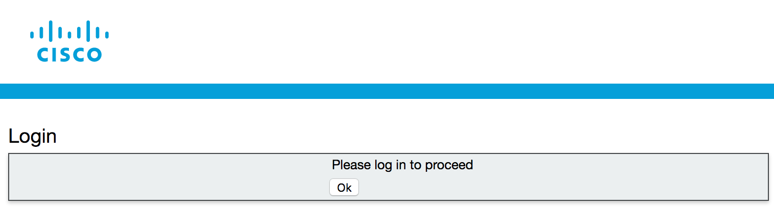
- Press Ok to get the username / password prompt.
- Then enter the credentials
(Username: admin,
Password: c1sco123)
and press Submit.

- You should see a reminder that the CMS server is currently unlicensed. You will upload licenses in the next
section.
- After pressing Ok, you should see the Overview screen, which shows basic system information
and fault conditions.
You can repeat this on all CMS servers if you like, just to make sure the web admin service is running properly. Feel free to connect to CMS 1B at https://cms1b.pod2.cms.lab:8443 and CMS 1C at https://cms1c.pod2.cms.lab:8443.
Web Bridge Configuration
If you plan to allow users to access their Spaces in Cisco Meeting Server via a browser, then you will need to configure the Web Bridge. It is the server role that enables users to manage and connect to their Spaces as well allow outside participants into conferences using only a WebRTC-enabled browser. New in version 2.9 of the Meeting Server software is a completely new version of Web Bridge which includes a new Meeting Server Web App and relies on a new intra-cluster communication protocol rather than XMPP for user authentication. We will be configuring the new version of Web Bridge (Web Bridge 3) in this lab and using the new Meeting Server Web App for browser-based calling instead of the more traditional WebRTC client which relied on XMPP services.
At this point in time, the legacy Web Bridge (Web Bridge 2) can be configured at the same time as Web Bridge 3. At some point in the future, however, support for XMPP and Web Bridge 2 will be removed from subsequent CMS releases. Boh Web Bridge 2 and Web Bridge 3 use a different protocol for user authentication. Web Bridge 2 relies on XMPP for authentication whereas Web Bridge 3 utilizes a new protocol called Callbridge to Webbridge (C2W). The benefit of the new Web Bridge 3 is that it does not require configuration of XMPP.
|
Configure Web Bridge on cms1a
The first step is to set the HTTPS certificates. These are the certificates that will be presented to web browsers so they need to be signed by a certification authority and the hostname needs to match. The certificate file required here is the full chain of certificates that starts with the end entity certificate (cms1a.cer) and finishes with the CA root certificate (cmslab-root-ca.cer). We combined these certificates to form our certificate chain (cms1a-fullchain.cer) in the Certificates section of the lab already. Start by configuring cms1a:
| Cisco Meeting Server Name | Password |
|---|---|
Next, enable the listening interface and port. In this case, you will use port 443, the default HTTPS port, on interface a. Remember when you configured the Web Admin service, you used port 8443 to leave port 443 available for the Web Bridge service.
Aside from communicating with web clients, the Web Bridge service must communicate with Call Bridge servers on the backend. To do that securely, we need to configure the Callbridge to Webbridge port to listen on. Remember that Callbridge to Webbridge is a new protocol used solely by Web Bridge for the purpose of user authentication and takes the place of XMPP. The port used can be any unused port, but it's a good idea to make the address/port accessible from the Callbridge(s) only. In this case we will set it to 4443.
Next, configure the C2W connection certificates. You need to configure the SSL Server certificates used for the C2W connection. These are what will allow Web Bridge to communicate with Call Bridge securely using the C2W protocol
The Web Bridge 3 C2W server expects Call Bridges to present a client certificate; Web Bridge 3 will verify whether to trust them using the trust bundle provided by the following command which we need to enter:
The redirect feature redirects connections destined to port 80 on the server to the Web Bridge listening port, 443 in this case. This allows users to enter the name of the CMS server without appending https:// to the URL. Note that if you configured http redirect for Web Admin previously, this would fail as you must decide which service you want port 80 redirected to. As Web Bridge is a user-facing feature, it makes sense to make accessing it as simple as possible.
Enable the Web Bridge service and ensure certificates are verified.
There are a couple additional steps to enabling Web Bridge 3. We need to configure the Call Bridge service to use C2W connections. C2W certificates are used for the connection between Call Bridge and Web Bridge 3. For the Call Bridge to make a C2W connection to a Web Bridge 3, we need to specify a C2W trust store to verify certificates against, so that when the certificates we configured above are presented by the Web Bridge 3, Call Bridge will trust them. We achieve this by configuring the command below:
Now we need to restart the Call Bridge service:
We can check the status of the Call Bridge and verify that the c2w certificate is visible:
Finally, check the status. The webbridge3 command indicates that the process is enabled. To see if the process is actually running, use the webbridge3 status command.
Configure Web Bridge on cms1b
Now that Web Bridge 3 is running on cms1a, configure it on the other two servers. Configure cms1b with the following commands:
| Cisco Meeting Server Name | Password |
|---|---|
| c1sco123 |
Enter the following commands on cms1b:
Now enter these commands for the Call Bridge to Web Bridge trust bundle on cms1b and restart Call Bridge:
Verify that the certificate verification succeeded and Web Bridge is successfully enabled.
Configure Web Bridge on cms1c
Finally, repeat these steps on cms1c.
| Cisco Meeting Server Name | Password |
|---|---|
| c1sco123 |
Enter the following commands on cms1c:
Now enter these commands for the Call Bridge to Web Bridge trust bundle on cms1c and restart Call Bridge:
Verify that the certificate verification succeeded for both services and Web Bridge/Call Bridge is successfully enabled.
Test Web Bridge Connectivity
Now that the Web Bridge service is running, you can point a browser to cms1a (https://cms1a.pod2.cms.lab) or any CMS server running the Web Bridge service and you should get the sign in screen like shown below.
At this point you have not completely configured the Web Bridge, but in order for calls to a Call Bridge to be aware of a Web App-based user, the Call Bridge has to be configured with the details of every Web Bridge. In scalable, redundant deployments, this must be done via the CMS REST API.
API Overview
Up until now, you have used the MMP (CLI) and web-based GUI to configure all CMS functions. For some small deployments, this may be all you need. However, for more advanced deployments, configuration via the API is required. Even in smaller deployments, it is useful to be comfortable with the basics of API configuration. You may never need to create a full-blown application for interacting with CMS programatically, but understanding API basics is critical to many functions on CMS that are not exposed via any of the other administrative interfaces.
Traditionally, an API, or Application Programming Interface, is a set of routines, protocols, and tools for building software applications. It is also a specification as to how software applications can interact. In some sense, it is similar to the set of commands you can run and results you get back with a command-line interface. The difference is that a CLI generates output that is generally unstructured and easy for humans to read. APIs generate structured output that makes it easy for other programs to process and interpret that data. With the right tools, you can manually interact with the API and easily read and interpret the data.
With a CLI, you can often enter ? or some other help flag to get more information about what commands are available. That doesn't exist in an API; therefore, the API developer's guide is crucial to understanding what commands are available and how to use them. You can view the API Reference Guide here.
Cisco Meeting Server relies on a Representational State Transfer (REST) API. It uses the HTTP (or HTTPS) protocol as the underlying transport and is a stateless, client-server protocol, which means that if you're familiar with web-based URLs and their structure, you will easily be able understand REST. In REST, there are 4 supported types of operations, called verbs: GET, POST, PUT, and DELETE.
Most REST APIs treat these verbs similarly. Here is what they do in the CMS API:
- GET - retrieves some information from the server.
- POST - creates something on the server, like a new user.
- PUT - modifies an existing object.
- DELETE - deletes an object
For example, if you want to query the system status for the uptime and software version, you would send a GET request to the CMS server. The API reference tells you that the uptime can be found by using the GET method on /system/status. Below is an exceprt from the CMS API Guide:
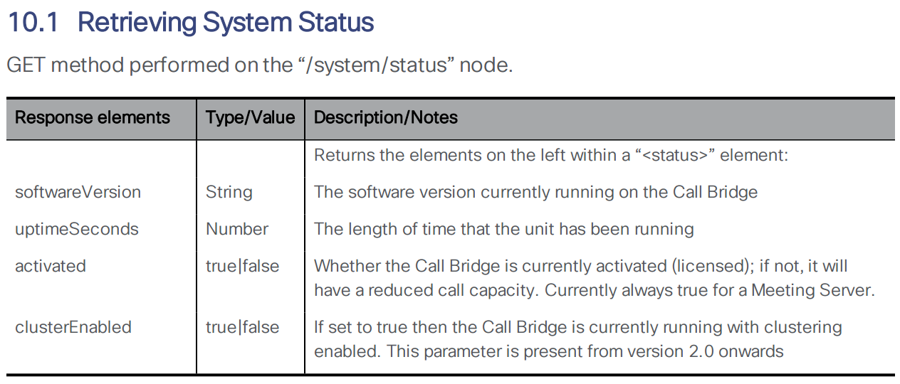
For the CMS API (and many RESTful APIs) all of these commands require /api/v1 as the base URL. This is documented in the API reference guide. The full URL to get the uptime of cms1a is therefore https://cms1a.pod2.cms.lab:8443/api/v1/system/status (username: admin password: c1sco123). You must use port 8443 because that is the Web Admin port you configured earlier. If you go to this link using a standard web browser, it will ask you to authenticate. You can use the same admin credentials you have been using for Web Admin. Once you do, you will get a result in XML format.
You can use a web browser to send basic GET requests like the one above, but for more complicated requests and to send a POST, PUT, or DELETE, you must use different tools. You could write a program using a variety of programming languages (Python, Java, .NET, and so on...), but there are ways to access the API without having to write a line of code. There are many applications available that allow you to interact with a REST API. One such application, that you will use in this lab, is called Postman. (Postman has already been installed for you, but for your reference, you can download Postman at https://www.getpostman.com/.)
Add API User
The default admin user has full access to the API, however it is best practice to create a dedicated user for API access. This is done from the MMP (CLI). Follow these steps to add an API user on each of the servers. These users are locally-significant, so you must configure the API user on each server individually.
| Cisco Meeting Server Name | Password |
|---|---|
On cms1a, enter the command user add apiadmin api to create a user named apiadmin with the api role. The password should be set to c1sco123:
You can use the user list command to confirm that the user was added.
The apiadmin account has already been created on CMS1b and CMS1c, so there is no need to configure anything there. Although the database is clustered in our lab, it is always a good practice to enable the same API account on all servers. For some parameters, such as ad-hoc conferencing and load balancing parameters, it is mandatory.
Postman Overview
Now you will get familiarized with the Postman application.
The first thing you should do is have Postman ignore SSL certificate verification. If you are using certificates signed by a trusted CA in your production environment, you may not need to do this; however, for our lab this is necessary. Perform these steps:
- From the Desktop of your laptop, launch the Postman application
- Click File > Settings
- On get General tab, change the SSL certificate verification option to OFF (greyed out).
- Click the X to close the Settings window.
Now you are ready to attempt your first request. Here is what the Postman UI should look like:
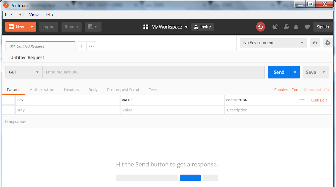
- Notice the default request type is GET. If you click on GET you will see a long list of methods supported by Postman. You will only be needing GET, POST, PUT, and DELETE for the CMS API. Leave this set to GET for now.
- To the right of GET, you should see a field that says Enter request URL. This is where you will enter the URL to which you send the query. Enter the following URL into this field: https://cms1a.pod2.cms.lab:8443/api/v1/system/status
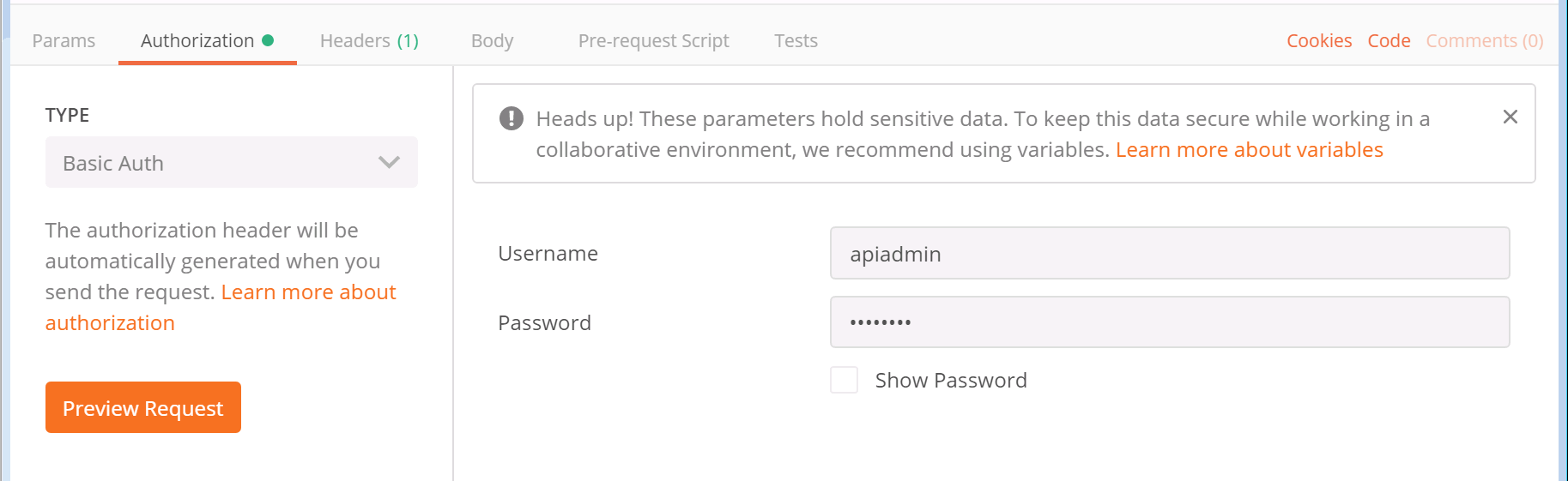
- CMS requires authentication for the query, so you must tell Postman to send the credentials along with the request. Below the GET button, there is an Authorization tab. Select it now.
-
For the Type of authorization, select Basic Auth from the drop-down
- After selecting Basic Auth, you should see a section to add a Username and Password. You should use the API user credentials you created earlier in this section. The username is apiadmin and the password is c1sco123.
- Finally, click the blue Send button.
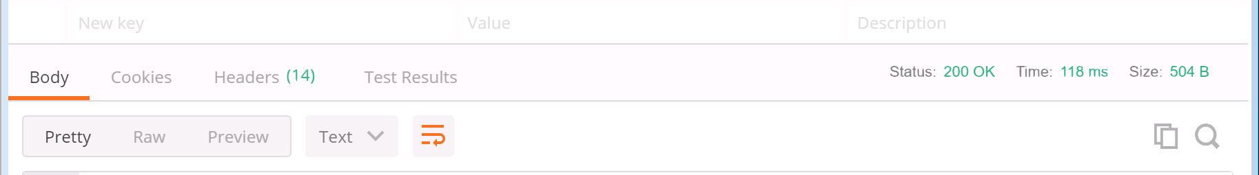
- The response is now shown in the pane below at the right side. You will notice that there is a Status message with a 200 OK. This is extremely important to check each time you send something, just to be sure the request was understood by the server, meaning there was no typo or an invalid parameter used, or even an authentication failure.
- By default, to the left in the Body, the results are shown in Raw format, however if you select the tab that says Pretty, you should see the system version and uptime in seconds, along with several other parameters. You'll notice clusterEnabled is true, since you have configured clustering already.


You have sent your first successful API GET request!
LDAP Introduction
Any meeting hosted by Cisco Meeting Server takes place in what is known as a Space. Before Cisco acquired Acano, this was referred to as a coSpace and in the API the older coSpace terminology still persists, so any API method mentioning a coSpace is referring to what we today call a Space. Spaces can be created either via the WebAdmin GUI or API.
Another way to create Spaces in CMS is via an LDAP agreement. Information from your LDAP directory (such as Active Directory) is used to create a permanent, personal Space tied to that particular user. These Spaces can be accessed and administered by the end-user using the browser-based WebRTC client or Cisco Meeting App on a desktop or mobile device. Authentication is still relayed back to the LDAP server.
LDAP Configuration
The Web Admin portal has an LDAP configuration section, but it does not expose all the more advanced configuration options and the information is not stored in the clustered database, so the configuration would have to be done manually on each server. If multiple LDAP agreements are required or if you deploy a database cluster, the API should be used to configure LDAP. You will use POST and PUT requests to accomplish this task.
Here is the LDAP server section of the API reference
LDAP methods reside in the API hierarchy under the /ldapMappings, /ldapServers and /ldapSources nodes in the object tree.
- The /ldapServers object defines an LDAP server's address/port information, along with username and password for accessing the server.
- The /ldapMappings object maps LDAP directory objects to corresponding elements in CMS. For instance, the DisplayName Active Directory LDAP field could be mapped to the nameMapping CMS parameter.
- The /ldapSources method ties everything together by associating an /ldapMappings object with an /ldapServers object while specifying an LDAP search base and possibly an LDAP filter.
Add an LDAP Server
Let's look at the API reference for the various LDAP configuration objects. To set up LDAP synchronization, you first need to create an LDAP server object. Here is the LDAP server section of the API reference:
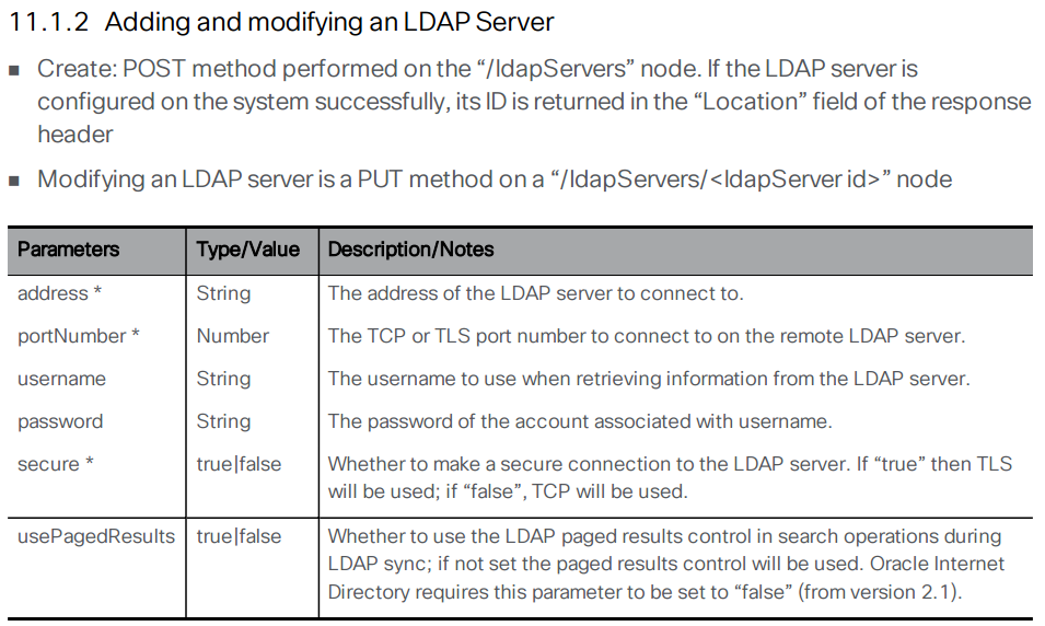
Using the above documentation, you can determine that the URL to access this API endpoint is https://cms1a.pod2.cms.lab:8443/api/v1/ldapServers. Because you are using the API, you only need to perform this configuration once on any node in the cluster and it will be replicated automatically.
Before you can send the necessary request, you must learn how to pass these parameters using Postman. Follow these steps to construct your POST request to add the LDAP servers.
- Launch Postman
- In the box that specifies the verb, make sure it is set to POST.
- Change the URL field to https://cms1a.pod2.cms.lab:8443/api/v1/ldapServers
- Click on the Body tab below the URL.
- If not already selected, select the x-www-form-urlencoded radio button. This takes the text we enter and, if necessary, converts certain characters into a format that the web service can understand.
- Based on the API documentation above, you must provide quite a few parameters. Click on the
Bulk Edit selection at the right of the Key/Value headers in order to enter
all the parameters at once.
- In the entry area below the entry mode selection changes to a free-form text box. Select and remove any old information from previous API queries.
-
Now let's review the required parameters. In Bulk Edit mode you can enter
them all at once with each key/value pair on a line separated be a colon. Click copy on the box at the
right below
Parameter / Key Value address 10.0.224.140 portNumber 636 username CN=ldap,CN=Users,DC=cms,DC=lab password c1sco123 secure true Bulk Edit Parameters to copy:address:10.0.224.140 portNumber:636 username:CN=ldap,CN=Users,DC=cms,DC=lab password:c1sco123 secure:true - Click Send. Your inputs and the result should look like this:

As with the last POST request you performed, there is no body to the response but you can see that the Status for the response is a 200 OK which indicates the request was successful.
The best way to verify your configuration is to simply leave the URL and everything as-is, but change the POST to a GET and click Send again. In the response area at the bottom, you should make sure the Body has the Pretty display setting selected. The response should look like this:
You can now verify that the data you entered was set properly on the server. You see the address, port, username, and secure setting. You do not see the password, which is obviously a security feature. Notice that you also see an ldapServer id field. This is important because it uniquely identifies this server configuration in the database. This ID is generated dynamically and therefore the ID on your server will not match the one shown in these screen shots. You will need this value later in the lab, however we will provide a link to retrieve it again at that time, so it is not necessary to record it at this time.
Add an LDAP Mapping
Now you can move to the next element, the LDAP mapping. The LDAP mapping maps attributes in the LDAP directory to attributes in CMS. Take a look at the API reference for the LDAP Mapping configuration.
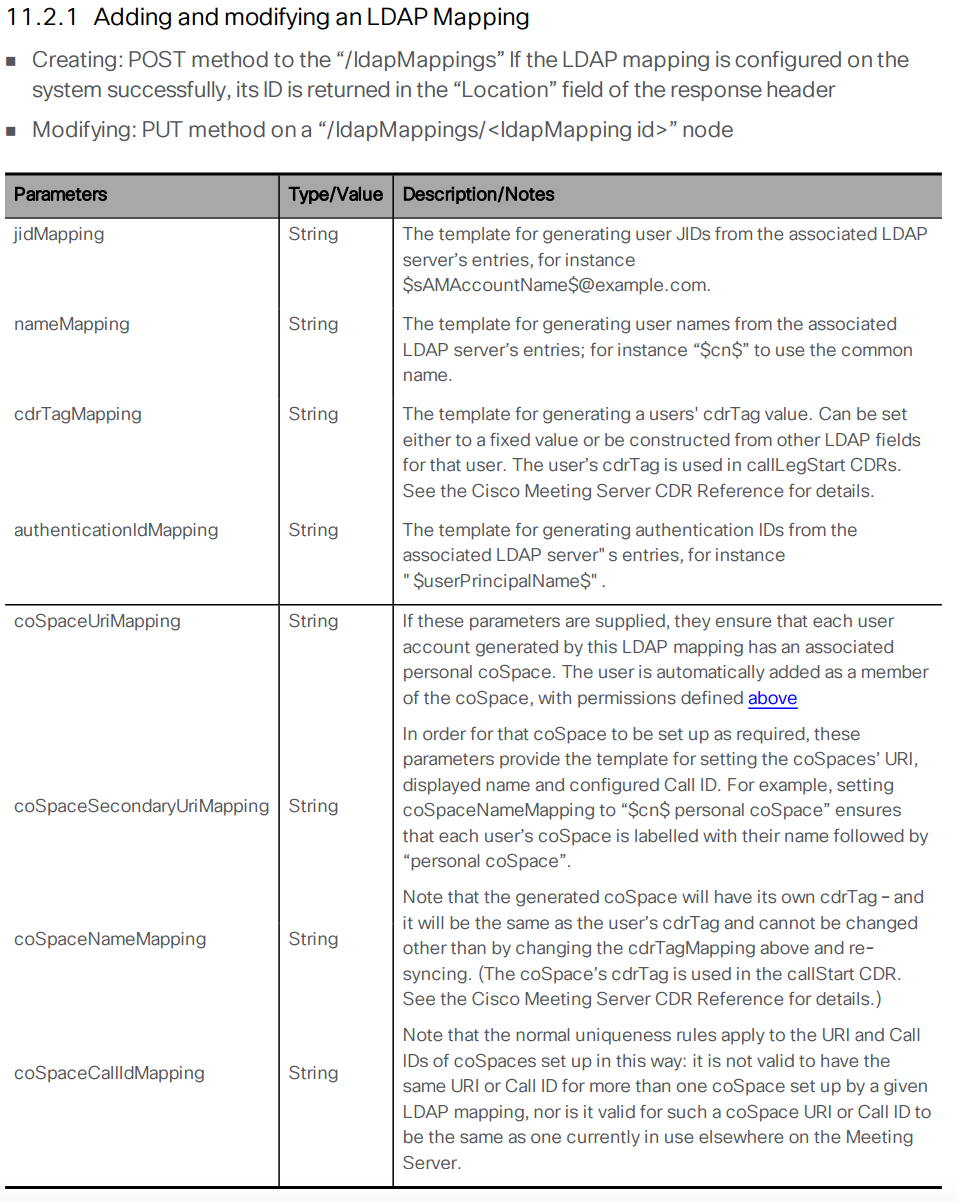
The following section takes you through configuring the LDAP Mapping. In the table below, the Parameter is the name of the attribute on the CMS side and the Value field represents the name of the object on the LDAP server. Follow these steps to configure your LDAP Mapping:
- Launch or switch to the Postman app
- Switch to the POST verb.
- Set the URL to: https://cms1a.pod2.cms.lab:8443/api/v1/ldapMappings
- Click on the Body tab.
- Underneath the Body header, make sure the x-www-form-urlencoded radio button is selected.
- Configure the following parameters for the request. Before doing so, select all of the old information
and remove that first.
Pay attention to the descriptions that explain why these specific parameters are being chosen below in
the table. Also notice that the actual parameters from the LDAP server are specified between two
dollar sign symbols ($). This allows you to use and modify the attribute by appending or applying a
transformation to the attribute that comes from the LDAP directory. Since there are quite a few
parameters, again it makes sense to take advantage of the Bulk Edit entry mode with the information
shown under the table.
The following are the parameters for Bulk Edit mode.Parameter / Key Value jidMapping $sAMAccountName$@conf.pod2.cms.lab
Description: The JID represents the login ID of the user into CMS. Because this is a Microsoft Active Directory LDAP server, the CMS JID maps to the sAMAccountName in LDAP, which is essentially the user's Active Directory login ID. Also notice that you are taking the sAMAccountName and appending the conf.pod2.cms.lab domain to the end of it because this is the login your users will use to log into CMS.nameMapping $displayName$
Description: This maps what is contained in the displayName Active Directory field the the user's CMS name field.coSpaceNameMapping $displayName$'s Space
Description: This will create a CMS Space name based on the displayName field, such as "John Smith's Space". This field, along with the coSpaceUriMapping field are what are required for a Space to be created for each user.coSpaceUriMapping $sAMAccountName$.space
Description: The coSpaceUriMapping field defines the user portion of the URI associated with the user's personal Space. As you will see later, certain domains are configured for dialing into a space. If the user portion matches this field for one of those domains, the call will be extended into this user's Space. This will become clearer when you complete the call routing portion of the configuration later.coSpaceSecondaryUriMapping $telephoneNumber|'/^.1919(.......)/7\1/'$
Description: This defines a second URI to reach the Space. You will use this to add a numeric alias to route calls into the imported user's Space as an alternative to the alphanumeric URI defined in the coSpaceUriMapping parameter. In this example, you want a number to be associated with the space based on the user's telephone number as defined in Active Directory. This command uses a transformation (similar to the UNIX sed program). The telephoneNumber values configured in Active Directory are in +E.164 format. For example, +19195551212. This transformation performs a match based on the first section, between the first two / signs, in this case ^.1919(.......). Just like in regular expressions, the ^ sign signifies the beginning of the string and the dot is a wildcard for any character. The parentheses are used to group portions of the match so that they can be used in manipulations later. In this example, ^.1919(.......) matches the number +19195551212. The next part of the line (between the / characters) is 7\1. This means that it will replace what it matched (+19195551212) with the number 7, plus the part of the match that was in parentheses, the last 7 dot's, or 5551212. In this example, if the number in active directory is +19195551212, the coSpaceSecondaryUriMapping will have a value of 75551212.
jidMapping:$sAMAccountName$@conf.pod2.cms.lab nameMapping:$displayName$ coSpaceNameMapping:$displayName$'s Space coSpaceUriMapping:$sAMAccountName$.space coSpaceSecondaryUriMapping:$telephoneNumber|'/^.1919(.......)/7\1/'$ - Once you have verified the above information is entered properly, click Send.
You should again see the Status indicate 200 OK. You can verify the configuration by switching from a POST to a GET and then clicking Send. You should see response similar to the response below:
You might be wondering why the output does not show you all the parameters you configured. You should see the ldapMapping ID that identifies the newly created object along with the jidMapping and the nameMapping. As often is the case, the other settings are only visible if you query the object itself. In order to query the object itself, you need to append the ID for the item you want to retrieve to the URL.
For example, if the ldapMapping id is <ldapMapping id="e5c2bfab-0616-4903-abbc-ea1d4301d116"> (it will be different in your results), copy the ID value (e5c2bfab-0616-4903-abbc-ea1d4301d116 in this example) and append it to the URL that is already in Postman. Your URL should end up looking something like this: https://cms1a.pod2.cms.lab:8443/api/v1/ldapMappings/e5c2bfab-0616-4903-abbc-ea1d4301d116. Once you have the new URL in place, click Send again.
Now you see the full configuration for the LDAP Mapping. Notice how the coSpaceSecondaryUriMapping some of the characters changed? That is due to the x-www-form-urlencoded method of entry we selected. All of this is documented in the API guide, but after a bit of familiarity and practice working with these APIs, you will find that this type of lookup is very common. You will need the value of the ldapMappings ID in the next part of the lab, but we will provide a link to retrieve it at that time, so there is no need to note it down right now.
Add an LDAP Source
An LDAP server and an LDAP mapping is configured. Now you need to tie the two together by creating an LDAP source. Take a look at the API reference for the LDAP Source configuration:
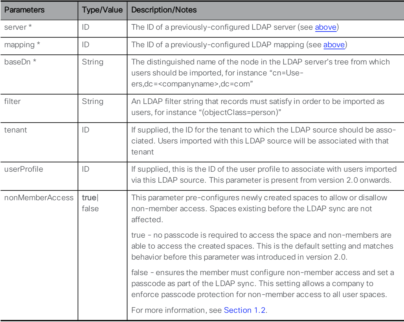
You can see that the LDAP Server and LDAP Mapping are required parameters for this API call, along with several other mandatory and optional parameters. To retrieve the necessary ID values, you will need to use the API. The links to retrieve them are provided below. Go through the following steps to configure the LDAP Source:
- Launch or switch to the Postman app
- Switch to the POST verb.
- Set the URL to: https://cms1a.pod2.cms.lab:8443/api/v1/ldapSources
- Click on the Body tab.
- Below the Body header, make sure the x-www-form-urlencoded radio button is selected.
- For this process, it may be easier to switch back to Key-Value Edit mode by clicking on the Bulk Edit button at the right side of the Postman screen.
- Review the following Key / Value pairs in the table below. Notice that the parameters entered in Bulk Edit
mode are retained, so you will likely show 5 Key / Value pairs from the previous POST request. This
request requires has 4, so just use the 'X' on the right of the
Key / Value pair you want to remove from the list and then overwrite the rest with the following
information:
Parameter / Key Value server ldapServer ID
This is the ldapServer id value from GET /ldapServers (username admin and password c1sco123)mapping ldapMappings ID
This is the ldapMappings ID value from GET /ldapMappings (username admin and password c1sco123)baseDn CN=Users,DC=cms,DC=lab filter (&(memberOf=CN=Pod2,CN=Users,DC=cms,DC=lab)(objectClass=person))
This filter looks at all LDAP/Active Directory objects that are of an objectClass of person that are members of a particular Active Directory security group, (CN=Pod2,CN=Users,DC=cms,DC=lab). Any user added to this group in Active Directory will be imported into CMS. - Once you have entered all the Key / Value pairs, click Send and verify a 200 OK response.
Perform LDAP Synchronization
Now that the LDAP configuration is done, you can perform a manual sync operation. There's two ways to do this - through the Web Admin GUI or through the API.
To perform the sync via the Web Admin GUI, do the following:
- Log in to the CMS server's Web Admin GUI at https://cms1a.pod2.cms.lab:8443 (username: and password: )
- Navigate to Configuration > Active Directory. You'll notice that the page has no configuration on it. This is because this page only shows locally configured LDAP information and does not show what is in the database.
- At the bottom of the page, select the Sync now button. This works even though there is no visible configuration of the LDAP configuration from the database.
- The sync should complete in a matter of seconds because you are only importing 4 users in this lab. To see the imported users in the Admin GUI, navigate to Status > Users. You should see four users imported.
- Navigate to Configuration > Spaces, where you can see the four Spaces created (and you could create additional ones)
Alternatively, you could have performed the sync using Postman by sending a POST request to the URL: https://cms1a.pod2.cms.lab:8443/api/v1/ldapSyncs, but at this point you won't see anything happening other than a 200 OK reply. You could also query the API via the browser for imported users and spaces using GET /api/v1/users and GET /api/v1/coSpaces.
Notice that for these Spaces, only the user portion of the URI is present. The domain or domains associated with these Spaces is not set here, but in the CMS Inbound call rules, which we will configure next.
Web Bridge API Configuration
In the Web Bridge section, we mentioned that you still need to configure the Call Bridge services to become aware of each Web Bridge service. Unless there is a direct one-to-one mapping of Call Bridges to Web Bridges, this configuration must be done via the API. This configuration requires us to use the POST request. Recall that you have deployed the Web Bridge 3 service on all three CMS servers.
API Reference
For this operation, you will need to use POST method of the /webBridges part of the API. It is worth pointing out that even though you just configured Web Bridge-related items on the CLI, they are not populated in the database. For instance, if you click to perform a GET on the webBridges object on CMS1a: https://cms1a.pod2.cms.lab:8443/api/v1/webBridges (admin / c1sco123), you'll see there are a total of 0 Web Bridges reported. This may come as a surprise as you have done some Web Bridge configuration already on the CLI. None of that configuration gets stored in the shared database, from which the API gets its information. To let Call Bridge know about the Web Bridge services you have enabled, you must add them to the database via the API.
Let us take a look at the requirements for a POST to the webBridges object in the API guide.
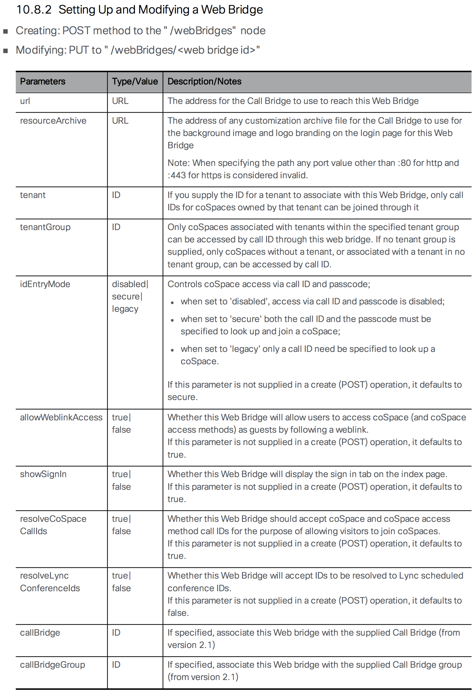
As is often the case, there are a lot of options. There is no * by any parameter, which indicates the field is required for the API, however to create a usable Web Bridge, you need to at least specify the url parameter. You are configuring the Call Bridge and telling it the URL of the Web Bridge. Prior to Web Bridge 3, this URL was in the form https://cms1a.pod2.cms.lab using the https:// protocol. If we were configuring Web Bridge 2, we could still use the HTTPS protocol, but with the newer Web Bridge 3 we will make use of the C2W protocol, so our URL will look like this: https://cms1a.pod2.cms.lab:4443 Recall that we configured Web Bridge to listen for C2W on port 4443, which is why we need to specify the port in this manner.
- In Postman, change the method to POST, because you are creating a new Web Bridge object.
- Set the URL to https://cms1a.pod2.cms.lab:8443/api/v1/webBridges. As with all requests, it could be sent to any server in the cluster and the data will be replicated.
- Just below the URL field, you should see a tab labeled Body. This option will be greyed out until you select the POST method. Select the Body tab to add parameters to the message body.
- Underneath the Body header, select the x-www-form-urlencoded radio button. With this checkbox selected, Postman automatically takes care of encoding the information for you. Alternatively, you could pick the Raw format and encode the information manually using something like https://www.freeformatter.com/url-encoder.html. Fortunately, Postman does this for you with this encoding setting.
- Based on the API documentation above, enter url under the Key heading. If there are other options, already present from a previous operation, clear them by clicking the X next to the row. Occasionally Postmay may be in Bulk Edit mode, you can switch back to Key/Value entry by clicking Key-Value Edit at the right. We'll use Bulk edit later.
- Enter c2w://cms1a.pod2.cms.lab:4443 next to it under the Value heading
- Click the blue Send button and verify a green 200 OK response.
You will notice the Body of the response will be blank on the bottom half of the screen, however Postman indicates the response status code next to the Status: field which should be 200 OK indicating that the request was processed successfully. You have now added one Web Bridge. Follow these steps to add the other two, then check the status:
- In Postman, verify that the UI still shows the POST operation and that the URL is correct, (https://cms1a.pod2.cms.lab:8443/api/v1/webBridges).
- Click on the Body tab if not already selected.
- Change Value for the url key to c2w://cms1b.pod2.cms.lab:4443, which is the URL for the second Web Bridge
- Click the Send button
- Now, assuming you got a 200 OK back, change the Value for the url key to c2w://cms1c.pod2.cms.lab:4443, which is the URL for the last Web Bridge
- Click Send
You should now have all the Web Bridges configured. Follow these steps to go back and confirm the three servers are entered properly.
- In Postman, change the method from POST to GET
- The URL should still be set to https://cms1a.pod2.cms.lab:8443/api/v1/webBridges. To prove that database replication is working, change the URL to point to a different Call Bridge. Change it to: https://cms1b.pod2.cms.lab:8443/api/v1/webBridges
- Click Send
If you followed the previous instructions correctly, you should now see all three Web Bridges on the list. You will notice that the output does not provide much detail. Many API requests will only return a UUID value for the object and you must query that object to get additional information about it. Note that the UUID values are unique and generated automatically, so the UUID values you see in this document will not match those in your environment. It is critical that any time you need a UUID value that you copy it from the output of your Postman client and not from this web page.
- In Postman, copy the long string called the webBridge id contained in the results of the previous GET request
- At the end of your URL in your GET request, put a forward slash ( /) character, and then paste the value of the id for your first Web Bridge. For example, the URL will look something like https://cms1b.pod2.cms.lab:8443/api/v1/webBridges/0a2ccba5-42ad-8e30-847c80c6e663 but with a different alphanumeric string.
- Click Send
This gives you the detailed configuration for this particular object. As you can see, some of the optional parameters that were specified in the API reference are shown. Referencing an object by ID as we just did is also how we will later modify (PUT) and/or delete (DELETE) objects. At this point, your Web Bridge and Call Bridge services should be functional. For it to be usable by end users, we will need to have accounts for them to log into.
CMS Inbound Call Settings
Now that you have configured Spaces that contain the user portion of the URI, you still need to configure the domains for which this Space applies. You do that via Incoming Call matching rules.
To determine how a call is handled, CMS only looks at the domain in the SIP Request-URI field. So if the SIP INVITE is destined to sip:user@domain.com, CMS only cares about the domain.com. CMS follows these rules for determining where to route a call:
- CMS tries to match the SIP domain to those configured on the Incoming call matching rules. Those calls can then be routed to any configured Spaces, logged-in users, internal IVRs, or to look up a conference on a Microsoft Lync / Skype for Business (S4B) / O365 integration.
- If there is no match on the Incoming call matching rules, CMS will try to match a domain configured in the Call forwarding table. If a match is made, the rule can explicitly reject a call or forward a call. At that time, CMS can re-write the domain, which is sometimes useful for calls to Lync domains. You can also choose to pass through the call, meaning that none of the fields will be further modified, or to use the internal CMS dial plan. If there is no match in the Call forwarding rules, the default behavior is to reject the call. Keep in mind that forwarding will still anchor the call at CMS, so you're essentially placing CMS in the middle of the call flow.
- Only forwarded calls are then subject to the Outbound call rules. These settings define the destinations where to send the calls, the trunk type (whether or not the new call will be Lync or standard SIP), and any transformations that may be performed, if pass-through is not selected in the call forwarding rule.
Incoming Call Rules
Configuring Incoming Call Settings is required to be able to receive a call on CMS. In this lab, you want all Spaces to have a dedicated domain, conf.pod2.cms.lab. So at minimum, you want calls to that domain to target the Spaces.
Follow these steps to configure the Incoming Call Settings on your CMS cluster:
- Log into the CMS admin for cms1a: https://cms1a.pod2.cms.lab:8443 (Username admin and Password c1sco123)
- Navigate to Configuration > Incoming calls
- Under Call matching, in the Domain name field, enter conf.pod2.cms.lab
- For the Priority enter 100. This will make this rule the highest priority on the list. Unlike other products, such as the VCS / Expressway, CMS uses the highest value to indicate the highest priority.
- Click Add New
Notice that there are currently no forwarding rules configured and that the catch-all rule is set to reject calls.
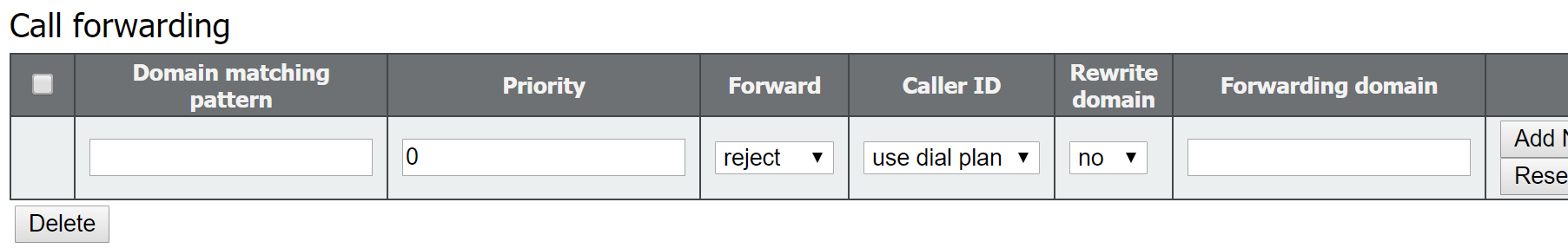
Allow Media Encryption
Aside from the inbound/outbound calling parameters, there is one SIP setting in CMS that need to be configured to allow for encrypted calls. Configure that by following these steps:
- Access CMS admin for cms1a: https://cms1a.pod2.cms.lab:8443
- Navigate to Configuration > Call settings
- For SIP media encryption, select allowed from the drop-down
- Click Submit at the bottom
We've done all we needed to do on the Cisco Meeting Server to accept calls. Next we will quickly take a look at outbound calling and then configure the Unified CM and Expressway-C to route calls to CMS.
CMS Outbound Call Settings
Not all deployments will require Outbound call settings; however for clustered Callbridge deployments, they are mandatory, because servers themselves use outbound SIP calling rules to place calls between Callbridge cluster nodes for the purposes of cascading calls. Outbound calls are also used when a client, such as CMA or endpoints with ActiveControl support, invite participants to a Space, as well as when calls are hair-pinned through CMS (in order to transcode between standards-based SIP and Microsoft SIP).
Regarding intra-cluster peer calls: if you recall, on the CMS Configuration > Cluster page, the Peer link SIP domain setting determines the domain portion for intra-cluster calls. If it is blank, as it is in your lab configuration, then the destination CMS's IP address is used (e.g. for CB_cms1a it is @10.0.102.51). If a peer link is configured, that domain must be routed exclusively to the CMS server node associated with that peer. This means that the domain is typically the FQDN of the destination Callbridge (e.g. for CB_cms1a it would be @cms1a.pod2.cms.lab). For this, an outbound rule must be configured in CMS with that domain/FQDN and indicate the destination of the call via the SIP Proxy setting. This SIP Proxy is usually an external call control, such as Expressway or Unified CM. This means that intracluster calls can be routed through an external call control agent as opposed to being sent directly between nodes.
You will need to add outbound routes for each of the 3 Call Bridges' IP addresses using the destination Call Bridge's IP address as the SIP Proxy to ensure those calls get sent directly to the respective node.
In addition to the intracluster calling rules, you will also add some rules that are specific to the call control integration. You will add the local Unified CM domain, pod2.cms.lab, as a standards-based SIP destination, but point it to the Expressway-C as the SIP Proxy. This will allow any outbound call or hairpinned call for that domain to be routed to the UCM cluster via Expressway-C. Finally, you will add a default, "catch-all", route. This rule allows clients (CMA and/or Jabber) to be able to invite participants using numeric numbers, not just URIs. When this type of call originates via Jabber, the domain of the Unified CM that the endpoint is registered to will be added when a number is dialed, therefore CMS needs to be able to reach the addresses of all UCM server nodes. The easiest way to do this is by configuring a default route from CMS.
Although you can perform these configuration tasks from the GUI (in the Configuration > Outbound calls section), we will show you how to use Postman to accomplish this task. Later you will verify the settings using the CMS admin GUI.
- Launch Postman and change the verb type to POST
- Change the URL field to https://cms1a.pod2.cms.lab:8443/api/v1/outboundDialPlanRules
- Click on the Body tab below the URL and select x-www-form-urlencoded
- Verify Bulk Edit entry mode is selected, so that you can paste the "Postman Bulk Edit Data" information into the window, press Send, and look for a 200 OK response.
- Verify the configuration by logging into the CMS admin: https://cms1a.pod2.cms.lab:8443 (Username admin and Password c1sco123) and access the Configuration > Outbound calls section.
| Domain | SIP proxy to use | Behavior | Priority | Description | Postman Bulk Edit Data |
|---|---|---|---|---|---|
| 10.0.102.51 | 10.0.102.51 | Stop | 200 | Route to CMS1a's IP address. Used for intra-cluster call routing. | domain:10.0.102.51
sipProxy:10.0.102.51
failureAction:stop
priority:200
|
| 10.0.102.52 | 10.0.102.52 | Stop | 200 | Route to CMS1b's IP address. Used for intra-cluster call routing. | domain:10.0.102.52
sipProxy:10.0.102.52
failureAction:stop
priority:200
|
| 10.0.102.53 | 10.0.102.53 | Stop | 200 | Route to CMS1c's IP address. Used for intra-cluster call routing. | domain:10.0.102.53
sipProxy:10.0.102.53
failureAction:stop
priority:200
|
| pod2.cms.lab | expc1a.pod2.cms.lab | Stop | 100 | Routes for UC domain to Expressway | domain:pod2.cms.lab
sipProxy:expc1a.pod2.cms.lab
failureAction:stop
priority:100
|
| <blank> | expc1a.pod2.cms.lab | Stop | 1 | Default route to Expressway. Used for outbound numeric dialing capability | domain:
sipProxy:expc1a.pod2.cms.lab
failureAction:stop
priority:1
|
For this lab we will not configure any Dial Transform rules. Dial transform rules ONLY affect outbound calls and they do so prior to routing the calls using the Outbound calling rules. Note that for clustered deployments, Dial Transform rules must be configured via the API, not the Webadmin GUI.
This completes the CMS Dial Plan configuration. We now need to configure our external call control entities to route calls to CMS. Since our call flow will be Jabber → Unified CM → Expressway-C → CMS, we will begin with the Unified CM.
Unified CM Call Routing Configuration
Configure Unified CM SIP Trunk to Expressway-C
Now that you have CMS Spaces created via the LDAP configuration and the inbound call settings set up to allow calls into CMS, you need to configure the call control devices to route the calls to CMS. The two most common integration options for CMS are either directly to the Unified CM cluster or directly to Expressway-C. While there are many reasons for doing one or the other or both, for this lab you will integrate CMS initially with Expressway, and Expressway will have a SIP trunk to the Unified CM cluster. This is the best option to support Microsoft interoperability via CMS because Expressway has the capability to identify and route calls based on the variant of SIP (either Microsoft or standards-based). For this design, you will initially have only one SIP trunk from the Unified CM to the Expressway-C. This would be used for all Business to Business calling as well as CMS traffic. Later we will consider the ad-hoc conferencing use case for Unified CM endpoints, which will require additional trunks from the Unified CM to CMS.
Begin by configuring the Unified CM SIP Trunk to the Expressway-C, including SIP Trunk Security Profile, followed by the necessary dial-plan components. In short, we will configure the following:
- SIP Trunk Security Profile is needed because we want all calls between the Unified CM and Expressway to be secure and encrypted.
- Secure SIP Trunk between the Unified CM and Expressway, utilizing a default SIP Profile for Expressway/VCS and normalization script.
- Route Group that includes this SIP Trunk.
- Route List that points to the Route Group.
- SIP Route Pattern to route any domain ( *.* ) to Expressway.
- SIP Route Pattern that blocks anything for the local UCM domain (pod2.cms.lab), so that calls to the local UCM domain are never extended to Expressway, thereby avoiding a potential routing loop.
If you would like to configure the Security Profile, SIP Trunk, Route Group, and Route List, continue with the following steps. If you would like to have this configuration created automatically for you, click HERE. You should see another window pop up with the results. If the addition is successful, you can skip the next few sections and move on to the Configure Dial Plan on Unified CM configuration.
SIP Trunk Security Profile
- Open the browser to the CUCM1a at https://cucm1a.pod2.cms.lab
- Log in with username admin and password c1sco123.
- Navigate to System > Security > SIP Trunk Security Profile.
- Click Add New
- Enter in the Name field.
- For Device Security Mode choose Encrypted
- In the Server Certificate Subject or Subject Alternate Name field enter
- Click Save
SIP Trunk to Expressway-C
- Now navigate to Device > Trunk
- Click Add New
- Chooose SIP Trunk as the Trunk Type
- Click Next
- Configure the following parameters:
Parameter Value Device Name EXPC1A-SIP-TRUNK Device Pool Default SRTP Allowed Checked Run On All Active Unified CM Nodes Checked Calling Search Space CSS_INBOUND_EDGE Calling and Connected Party Info Format Deliver URI and DN in connected party, if available Destination expc1a.pod2.cms.lab Destination Port 5061 SIP Trunk Security Profile Encrypted SIP Trunk Profile for Expc1a SIP Profile Standard SIP Profile for Cisco VCS Normalization Script vcs-interop - Click Save
- Click OK on the popup
- Click Reset
- On the Device Reset popup click Reset
- Click Close
The SIP trunk should be put into a Route Group, which needs to then be placed in a Route List. These should already be configured for you (called RG-EXPRESSWAY1 and RL-EXPRESSWAY1), however if you need a refresher, expand the following steps.
Route Group
- In the Unified CM navigate to Call Routing > Route/Hunt > Route Group
- Click Add New
- For the Route Group Name enter RG-EXPRESSWAY1
- Select the EXPC1A-SIP-TRUNK device from the Available Devices and click Add to Route Group
- Click OK if you get a popup
- Click Save
Route List
Now configure the Route List.
- In the Unified CM navigate to Call Routing > Route/Hunt > Route List
- Click Add New
- For the Name enter RL-EXPRESSWAY1
- For the Cisco Unified Communications Manager Group, choose Default.
- Click Save
- In the Route List Member Information box, click Add Route Group
- Select RG-EXPRESSWAY1 as the Route Group
- Click Save
- Click Ok in the pop-up
- Check Run On All Active Unified CM Nodes
- Click Save, to save the Route List configuration.
Configure Dial Plan on Unified CM
Configure Route Patterns on Unified CM
From the LDAP import, we created Spaces for all of our users with a 7XXXXXXX pattern. Unified CM needs to have a Route Pattern to be able to call those Spaces.
- Log in to the CUCM1a at https://cucm1a.pod2.cms.lab (username: admin and password: c1sco123)
- Navigate to Call Routing > Route/Hunt > Route Pattern
- Click Add New
- In the Route Pattern field, enter 7XXXXXXX
- For Route Partition, select PT_EXPRESSWAY
- For Gateway/Route List, select RL-EXPRESSWAY1
- In the Call Classification box, select OnNet
- Uncheck the Provide Outside Dial Tone selection
- Click Save
This will allow calls to that numeric range (7XXXXXXX) to be extended to Expressway.
Configure SIP Route Patterns on Unified CM
With CMS primarily integrated to Expressway, the Unified CM dial-plan is essentially a Business-to-Business type of dial plan. Since we want to allow users to call any remote domain, we will use wildcards. We will be careful not to allow anything that matches the local Unified CM/Jabber domain, otherwise you could potentially create a loop, since the Expressway is configured to route that domain right back to the Unified CM. You will configure a wildcard pointing to Expressway and a block pattern for the local domain.
- Log in to the CUCM1a at https://cucm1a.pod2.cms.lab (username: admin and password: c1sco123)
- Go to Call Routing > SIP Route Pattern
- Click Add New
- Configure the following parameters:
Parameter Value IPv4 Pattern Route Partition PT_EXPRESSWAY SIP Trunk/Route List RL-EXPRESSWAY1 - Click Save
Now that you are routing all domain calls that do not match a local URI to the Expressway-C, you must take into account that some URIs that match the local domain pod2.cms.lab, but no user exists for that URI, will also match. You want this traffic to be dropped. Perform the following steps to configure the SIP Route String so that calls to invalid local URIs will not be routed to the Expressway-C.
- Go to Call Routing > SIP Route Pattern
- Click Add New
- Configure the following parameters:
Parameter Value IPv4 Pattern Route Partition PT_EXPRESSWAY SIP Trunk/Route List RL-EXPRESSWAY1 Block Pattern Checked - Click Save
Expressway-C Call Routing Configuration
Now that the Unified CM can route SIP calls to Expressway, we can focus on the Expressway dial plan. Cisco Expressway has the capability of routing calls, among other things, based on the SIP variant detected. Specifically, it can distinguish between Microsoft SIP calls and standards-based SIP calls, such as those originating from Unified CM and Jabber. Initially, we will use this capability so that we only route standards-based SIP calls for our UC domain (pod2.cms.lab) to the Unified CM. Any SIP call matching the CMS domain (conf.pod2.cms.lab) will be routed to CMS.
For this lab, your Expressway-C should already be configured with a system name, valid NTP server, and an internal DNS server. The server certificate and certificate authority certificates are installed as well. Additionally, it has the Traversal Zones for Business to Business communication via the Expressway-E set up, as well as a zone to the Unified CM.
What needs to be configured:
- Add a Zone for each Cisco Meeting Server in the cluster
- Add a Search Rule for calls going to Unified CM
- Add Search Rules for calls going to CMS
Expressway Zones for Cisco Meeting Server
In order to route calls to Cisco Meeting Server, Zones are required. While it is possible to create a single Zone pointing to each of the CMS servers in the cluster and obtain a basic level of redundancy, this currently does not handle load balancing as implemented in CMS, because if CMS rejects a call when the capacity of the server is exceeded, the SIP 488 message returned by CMS will not cause Expressway to route the call to the next Zone member. Because of this limitation, one Zone per CMS server in a cluster is required. Expressway Search rules will then be configured to hunt through each zone in a top-down fashion.
- Open the browser to the Expressway-C at https://expc1a.pod2.cms.lab
- Log in with username admin and password c1sco123
- Navigate to Configuration > Zones > Zones.
- Click New
- Enter in the Name field
- For the Type, select Neighbor
- Under the H.323 section, turn the Mode to Off
- In the Location section, for Peer 1 address enter the CMS1a FQDN, .
- In the Advanced section, select a Zone profile of Custom
- Verify the Meeting Server load balancing is On
- Click Create Zone
Next, the exact same thing needs to be configured for CMS1b and CMS1c. You can click HERE to have it done for you, otherwise, repeat the above steps, simply changing the name of the Zone (to and ) and, of course, the Peer 1 address to and respectively.
From the Zone list, you can refresh this information a few times. Eventually, all Zones should go to the Active state.
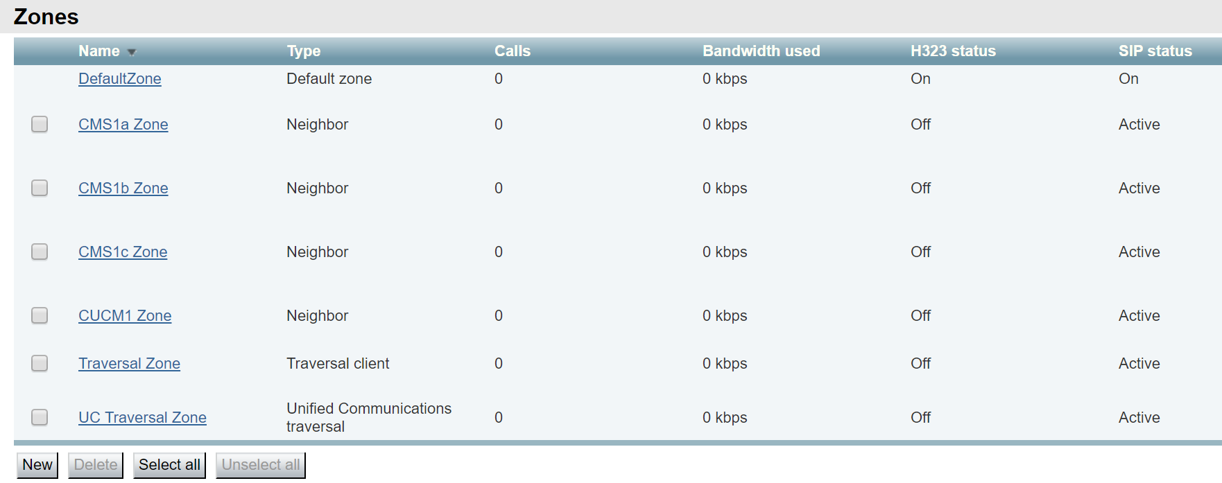
Search Rule for Unified CM Domain
Next we can focus on the dial plan. Expressway needs to route calls for the Unified CM domain to UCM and calls to the CMS domain to CMS.
In Expressway, SIP routes are configured using Search Rules. Begin with the Search rule for the Unified CM domain, pod2.cms.lab. Setting this rule is fairly straightforward, however, note that since the Unified CM can only support standards-based SIP calls, we will limit the rule to just that type (and ignore any call to the Unified CM domain that is a Microsoft-type SIP call.
- Navigate to Configuration > Dial plan > Search rules.
- Click New
- Configure the following:
Parameter Value Rule Name Priority 100
Note: Remember that the lower the number the higher the priority in the Expressway productProtocol SIP SIP Variant Standards-based Mode Alias pattern match Pattern type Regex Pattern string
Note: This matches any of the following domains: cucm1a.pod2.cms.lab, cucm1b.pod2.cms.lab, or pod2.cms.lab
For help with regular expressions, Expressway has a tool under Maintenance > Tools > Check Pattern. Also, sites like https://regex101.com are helpful.Pattern behavior Leave On successful match Stop
If the call does not complete to this zone, do not continue hunting.Target CUCM1 Zone
- Click Create search rule
Search Rule for CMS Domains
Next we can add the Search rules for each of the CMS Zones. We will do these sequentially, so that in case of contention, Expressway will try them all in order.
- Navigate to Configuration > Dial plan > Search rules.
- Click New
- Configure the following:
Parameter Value Rule Name Priority 100
Protocol SIP Mode Alias pattern match Pattern type Regex Pattern string .*@conf\.pod2\.cms\.lab.* Pattern behavior Leave On successful match Continue
Because we want it to try CMS1b, if necessaryTarget CMS1a Zone
- Click Create search rule.
Now we can configure the CMS Domain to CMS1b rule. Except for the target and a higher Priority, it will be identical to the To CMS1a Zone
- Since this is nearly identical to the last rule, find the rule just created called CMS Domain to CMS1a and at the right of the row, click Clone.
- Change the Rule Name to
-
Change the Priority to 101.
The priority is very important. If Expressway matches two rules with the same priority, then the call would be forked to both destinations. In this lab you will see us use the same priority for many rules, but either the domain or SIP variant will always be different. - Change the Target to CMS1b Zone.
- Click Create search rule
Finally we configure the CMS Domain to CMS1c Search rule.
- Since this is nearly identical to the last rule, find the rule just created called CMS Domain to CMS1b and at the right of the row, click Clone.
- Change the Rule Name to
- Change the Priority to 102
- For On successful match, select Stop.
- Change the Target to CMS1c Zone.
- Click Create search rule
Transform for Numeric Calls to CMS
One other call flow to consider is numeric dialing to a Space. The LDAP-imported Spaces were created with a number pattern of 7502XXXX. When Unified CM routes a numeric call, it will append the destination IP address or FQDN, depending on what is specified in the outbound SIP trunk. This means that a call destined to 75020001 will be sent to Expressway with a URI of 75020001@expc1a.pod2.cms.lab. We will add a Transform in Expressway to re-write the call so that it becomes 75020001@conf.pod2.cms.lab, for which the configured Search rules will route the call to CMS.
- Open the browser to the Expressway-C at https://expc1a.pod2.cms.lab and log in with username admin and password c1sco123
- Navigate to Configuration > Dial plan > Transforms.
- Click New
- For the Pattern type, select Regex
- In the Pattern string field, enter (7502....)@expc1a\.pod2\.cms\.lab.*
- For Pattern behavior, select Replace
- For Replace string, enter \1@conf\.pod2\.cms\.lab.*
- Click Create transform
Now calls to CMS can be tested.
Test CMS Calls
At this point the Unified Communications Manager and Meeting Server have all the configuration needed for you to be able to place a call from Jabber on your laptop into a space. Jabber should already be launched and registered. Test dialing by URI by calling pod2user4.space@conf.pod2.cms.lab directly from the Jabber client.
|
|
|
|
Once that is successful, it's worth emphasizing that ActiveControl has negotiated. This means that the Jabber client realizes it is in a CMS conference. The regular ad-hoc conference button will be greyed out, but you can invite other users.
-
Click Invite Participants
- In the search enter Pod2 User1
- Now hover over the Pod2 User1 entry and click the green call icon.
-
Click the Work URI (pod2user1@pod2.cms.lab) for that user to place the outbound
call from CMS to the user.
- This user will auto-answer, so as seen in the participant list, we have added them to the conference. If we right-click on the participant entry for Pod2 User1, we see the Expel option that gives us the ability to remove this participant from the conference.
Features such as the active conference participant list, ability to remove participants, as well as the layout
features, are available because we have a version at or later than Jabber 12.5 and have allowed ActiveControl on
our SIP Trunks by enabling Allow iX Application Media on the SIP Profile applied to our trunks
to CMS.
A number of these capabilities can be further customized in CMS. For instance, you will now add the ability to mute a remote participant in a conference by accessing the CMS API via Postman.
Leave the current conference up for the next section, since these changes are dynamic and you will make them system-wide:
- Launch Postman
- Make sure you have still specified the GET verb.
- Change the URL field to https://cms1a.pod2.cms.lab:8443/api/v1/system/profiles
- Click Send. Your Postman screen and the result should look like this:
- From the output, copy the callLegProfile id. This is the ID of the system profile, the one calls use by default.
- Change the URL field to https://cms1a.pod2.cms.lab:8443/api/v1/callLegProfiles/
- Paste this callLegProfile id at the end of the URL
- Change the verb from GET to PUT since you will now modify this existing callLegProfile.
- Click on Body
- Make sure x-www-form-urlencoded is selected
- Remove any old Key / Value pairs by clicking on the X next to their row.
- For the Key enter muteOthersAllowed
- In the Value field next to muteOthersAllowed, enter true
- Click Send. Your Postman screen and the result should look like this:
- Verify that you received a 200 OK message back, then return to the active Jabber call (or start another conference as in the previous steps if disconnected).
-
When you hover over the other participant in the conference, Pod2 User1. You
should now see the mute icon, which will turn red when clicked.
- Disconnect the remote user by right-clicking on on the user's name and selecting Expel in the context menu that .
-
Hover over the remaining video window and click the
 button to disconnect the call.
Keep in mind that this change was made to the callLegProfile associated with the systemProfile. If you recall the hierarchy below, this means that every Space, as long as it does not have a different callLegProfile that overrides this behavior, will inherit the ability to muteOthersAllowed property.
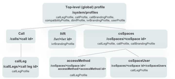
Branding
Branding in CMS refers to customization of prompts and backgrounds for Call Bridge and Web Bridge in order to present a user experience that reflects your company more personally. In some cases, it can enhance the experience for your users, such as when removing the prompts that play when joining an ad-hoc conference bridge call. In earlier versions, branding required a separate license and could only be hosted on an external web server. Since CMS 2.4, no special license is required for branding and CMS version 2.5 introduced the ability to host a single set of branding files on the Call Bridge server itself. This is the scenario we will configure in this lab.
There are 4 different types of customizations:
- The CMS Web App sign in background image, sign in logo, text below sign in logo and the text on the browser tab
- IVR messages
- SIP/Lync call messages
- Some text on the meeting invitation
In each case, a ZIP file with the appropriate audio, images, and/or configuration files is required. If an image is larger than the specified maximum size or a particular audio file is missing (even if you didn't intend to modify that file), there is no attempt to fall back to default resources. That means that a missing background image from a customization file will result in a black background. A missing prompt file will result in blank audio in its place.
In this lab, we will illustrate changing the default background image of the Spaces we call in to. To do this, we only need to create a zip file with the relevant images, and then TFTP the file to all of the CMS servers running the Call Bridge service (and then restart Call Bridge).
Perform these steps:
- Download the default US-English prompt set for Call Branding. These are also available from the Cisco web site under Cisco Meeting Server 2.4 and later Call Branding example - US
- Download a custom background image.
- Double-click the CMD icon on the Desktop (or open up a local command prompt by entering cmd in the search or Start > Run box.
- Change to the Downloads folder by entering cd %userprofile%\Downloads
- Expand the Prompts file. This file contains all the SIP and IVR call customization files. Enter: PowerShell Expand-Archive -Path CMS-2-4_callBranding_example_US.zip -DestinationPath call_branding -force
-
Copy the clus2020-cms-background.jpg file over the default call_branding\background.jpg by
entering
copy /Y clus2020-cms-background.jpg call_branding\background.jpg
- Now that we have all the necessary files we need in the call_branding folder, we can compress it to call_branding.zip. Enter: PowerShell Compress-Archive -Path call_branding/*.* call_branding.zip -force
-
You now have a single call_branding.zip file containing all the default prompts, plus the
updated background.jpg image. Next, we copy the file to each of the CMS CallBridge servers.
psftp admin@cms1a.pod2.cms.lab c1sco123 put call_branding.zip exit psftp admin@cms1b.pod2.cms.lab c1sco123 put call_branding.zip exit psftp admin@cms1c.pod2.cms.lab c1sco123 put call_branding.zip exit
-
Now we need to restart all the CallBridge services on each CallBridge.
Cisco Meeting Server Name Password c1sco123 c1sco123 c1sco123 - First connect to
- Enter the callbridge restart command. Other customizations, such as WebRTC customizations, also require restart of the WebBridge service.
- Next connect to
- Enter the callbridge restart command. Other customizations, such as WebRTC customizations, also require restart of the WebBridge service.
- Finally, connect to
- Enter the callbridge restart command. Other customizations, such as WebRTC customizations, also require restart of the WebBridge service.
- To make sure there are no issues or missing files, log into Webadmin on CMS1a (username: admin, password: c1sco123) and see if there are any Fault conditions registered on the Status > General.
- Now place a call to pod2user4.space@conf.pod2.cms.lab and observe the updated Space background.
|
|
|
|
SECTION COMPLETE!
You've finished this portion of the lab. We have multiple other optional lab sections, depending on your time and interest, to continue on.
-
Understand other CMS features, such as:
- Spaces, to understand more about how Spaces are organized and configured.
- Ad-hoc conferencing and integration with the Unified CM
- CallBridge Groups for load balancing calls
-
Explore Cisco Single Edge with Cisco Expressway and CMS:
- Learn about deploying the external WebRTC Web App using Cisco Expressway, to provide external users the same Web Bridge capability.
- Configure advanced Business-to-business calling with Skype for Business gateway calling.
- Investigate a Microsoft on-premise integration example, where you will learn about what is needed to configure a dual-home conferencing experience.
- Experience Cisco Meeting Management (CMM), our free product to allow video conference administrators to provide white-glove conferencing services.
Call Bridge Groups
While a Cisco Meeting Server Call Bridge cluster provides a scalable, redundant conferencing service, by default, CMS does not always make the most efficient use of the conferencing resources available to it and, at the same time, may simply allow a particular server to become over-subscribed.
For example, for a meeting with three participants, each participant may end up on three different Call Bridges. In order for those three participants to be able to participate in the same Space, the Call Bridges will automatically set up connections between all the servers to make the user experience seem like they are all on the same server. The unfortunate downside of this is that a single 3-person conference now consumes 6 media ports of capacity. This is obviously an inefficient use of resources, albeit a worst-case scenario. Additionally, when a Call Bridge is truly overloaded, the default mechanism is to continue accepting calls and provide service at a reduced quality to all callers on that Call Bridge.
These challenges are addressed by the Call Bridge Group feature. This feature was introduced in version 2.1 of the Cisco Meeting Server software and has been enhanced to support load balancing for both inbound and outbound calls, Cisco Meeting App (CMA), including WebRTC participants. This lab will introduce the principles and focus on load balancing of inbound calls.
To solve the over-subscription problem, three configurable load limits for each Call Bridge were introduced:
- loadLimit - This is the numeric maximum load for a particular Call Bridge. Each platform has a recommended load limit value, such as 700,000 for a CMS2000 (in version 2.6), 96,000 for a CMS1000 and 1,250 per vCPU for a Virtual Machine. Different calls consume a certain amount of load based on the resolution and frame rate of the participant.
- newConferenceLoadLimitBasisPoints (defaults to 50% of loadLimit) - sets point limit after which new conferences are rejected
- existingConferenceLoadLimitBasisPoints (defaults to 80% of loadLimit) - point value after which participants joining an existing conference will be rejected
While the feature was designed to address call distribution and load balancing, other entities, such as TURN servers, Web Bridge servers, and Recorders can also be assigned to Call Bridge Groups so that they, too, can be properly grouped for optimal usage. If any of those objects is not assigned to a Call Bridge Group, they are assumed to be available to all servers without any particular priority.
With these simple values, there are a few things to keep in mind:
- A "rejected" call really means that when extending a call to an overloaded Call Bridge, the CMS responds with a SIP 488 ("Not Acceptable Here") message. To the Unified CM, this is not a terminal failure, it simply tells Unified CM to route the call to the next available destination, controlled by standard Unified CM routing (implemented via Route List/Route Groups, Local Route Groups, etc). Not until all possible destinations are exhausted will the caller be rejected in some fashion.
- Distribution calls are never rejected. If a caller does get routed to a Call Bridge that is not hosting a call into a Space that is active on one or more other Call Bridges, this Call Bridge will always be able to join the caller to the Space hosted on another server.
- The amount of load a given call consumes is determined by the resolution, frame rate, etc, that the individual call leg has negotiated. These parameters are not configurable.
The other primary goal of the Call Bridge Group feature is to make sure that all participants within a Call Bridge Group accessing a particular Space will all be connected to the same server, thereby eliminating excessive distribution of calls between Call Bridge nodes. To make this happen, when a call is extended to a CMS to join a Space, the server will communicate with the other Call Bridge servers to determine which server is currently hosting the meeting. If it determines that a Space is being hosted by another server within the Group, then the destination serer will send a SIP INVITE with a Replaces header, essentially telling the Unified CM to transfer the call to it.
At the same time, if a meeting is hosted by a Call Bridge in one Call Bridge Group and someone wants to join from a different region and therefore dials in via a second Call Bridge Group, those calls will always be distributed between the servers in the different regions. The goal is to aggregate the calls for a Space on a single server within a given Call Bridge Group.
This feature imposes requirements on the call control. For Expressway, this means version X8.11 or later and the Meeting Server Load balancing option configured on Zones pointing to CMS, which is the default for all Zones using the Custom Zone profile.
For a CMS integration to Unified CM, this means Accept replaces header must be enabled in the SIP Trunk Security Profiles and each SIP trunk to CMS must have a Rerouting Calling Search Space configured to allow the call be be transferred between CMS SIP trunks.
Sample Test Call
To illustrate this problem you will add Search Rules to bypass Expressway that allow you to place a call to a CMS node's FQDN and have it be routed ONLY to that node specifically with no failover or redundancy.
To add these Search Rules, click HERE. You should see another window pop up with the results. The configuration may take a few seconds to complete.
Now you will place calls to the same Space from Jabber on the laptop, PC1 and PC2 to pod2user4.space using domains cms1a.pod2.cms.lab, cms1b.pod2.cms.lab, and cms1c.pod2.cms.lab
- Make sure you have Remote Desktop sessions up on PC1 (10.0.102.91) and PC2 (10.0.102.91)
- Using Cisco Jabber on your laptop, click/call our created Space at pod2user4.space@cms1a.pod2.cms.lab
- Check the active calls on CMS1A and you should see the call placed from Pod2 User 4: https://cms1a.pod2.cms.lab:8443/calls.html
- From PC1's Jabber client, call the same Space, but this time send the call to CMS1B by dialing pod2user4.space@cms1b.pod2.cms.lab. Check the call status on the CMS1A again. This call will use a different CMS server, in this case CMS1B, since we sent the call directly to the CMS1B host.
- From PC2's Jabber client, call the same space, but to CMS1C by dialing pod2user4.space@cms1c.pod2.cms.lab.
- You should now see each call on its own CMS, with two distribution links to the other two CMS nodes: All with username: admin password: c1sco123
- When finished, disconnect the remote callers first. Hover over each user in the participant list, right-click and select the Expel option.
-
Once all remote callers have been disconnected, hang up yourself by hovering over the video window and
clicking on the button
The behavior illustrated above is an inefficient use of resources and is what we will be addressing by placing CMS servers into Call Bridge groups. By using Call Bridge Groups, calls for the same Space will be kept on a single Call Bridge.
Creating Call Bridge Groups
There are three parts to configuring Call Bridge Groups and load balancing in CMS: creating Call Bridge Groups, enabling load balancing and relevant parameters; and applying the Call Bridge Group to the Call Bridges.
The first step to implementing Call Bridge Groups is to decide how to group your Call Bridges. You may choose to create groups by region, datacenter location, country, etc. For this lab, you will create a group called East, consisting of cms1a and cms1b, and a group called West, consisting only of cms1c.
Take a look at the API reference for the Call Bridge Group feature:
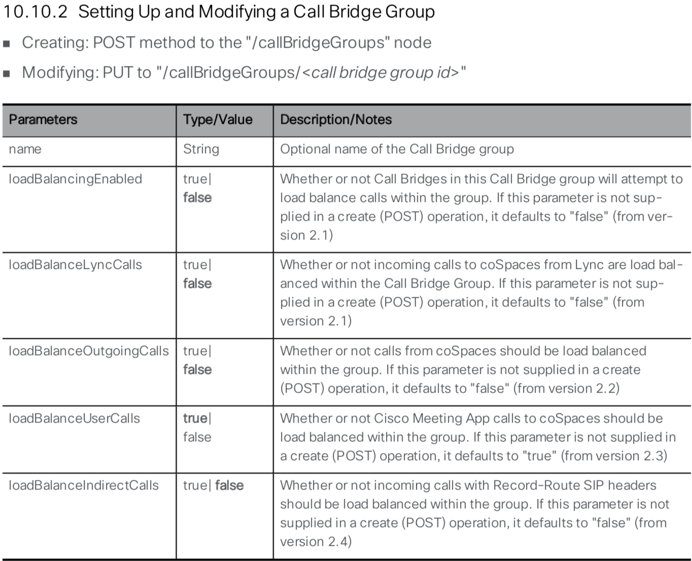
A quick look at the API reference shows that you need to give the new Call Bridge Group a name and can set loadBalancingEnabled to true. Since you are integrating with Cisco Expressway, you also need to set loadBalanceIndirectCalls to true.
- In Postman, the query type should be set to POST
- In the URL field, overwrite the existing URL with https://cms1a.pod2.cms.lab:8443/api/v1/callBridgeGroups
- Below the URL line, click on the Body tab
- Ensure the x-www-form-urlencoded box is selected
-
In the Body section, switch to Bulk Edit mode. Make sure any existing
information is removed and paste in the following:
name:East loadBalancingEnabled:true loadBalanceIndirectCalls:true
- Click Send
- Now add the West Call Bridge Group. In Postman, in the Bulk Edit portion, change East to West, or simply paste the following into the window, removing the previous information completely:
- Click Send
- Verify the two locations were created by changing the operation from POST to GET and click send. If the Body tab is selected in the results, you should see the two groups as below. Alternatively, you could click GET /callBridgeGroups to use your browser directly to retrieve these group IDs.
- Notice not all information is present in these results. Copy the ID field for the East Call Bridge Group from the popup window and append it to the base URL. The base URL is https://cms1a.pod2.cms.lab:8443/api/v1/callBridgeGroups. The completed URL will look something like https://cms1a.pod2.cms.lab:8443/api/v1/callBridgeGroups/5ff3e8f3-b234-475c-809d-e363a3289bcf
- Click Send
You have enabled load balancing at the Call Bridge level but you have not yet configured any of the load parameters, so they are set to the default values. You can look at the current settings by performing an API query. The following API reference documentation shows how to retieve these values:
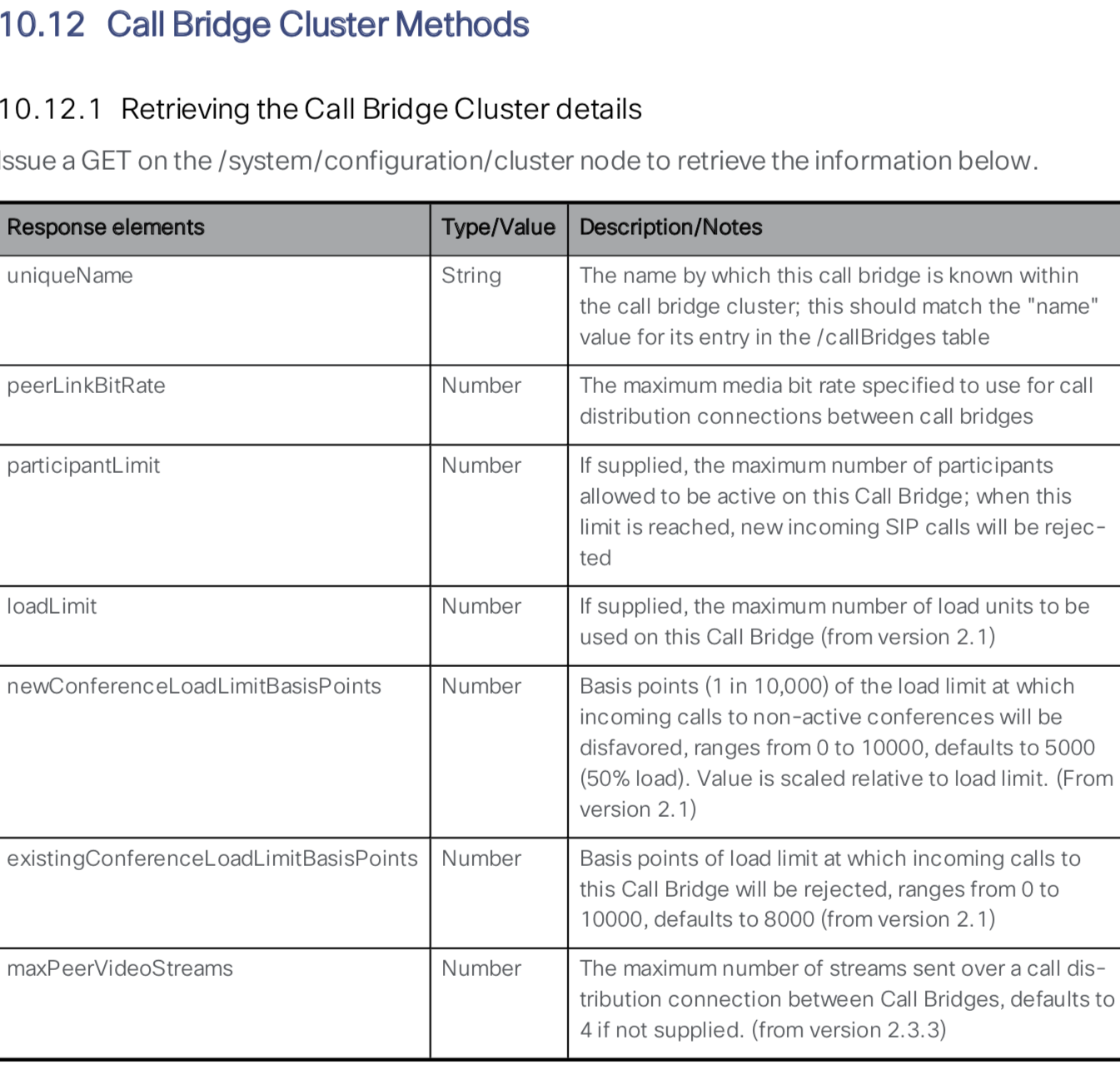
Follow these steps to perform a GET request to retrieve the Call Bridge Cluster details:
- In Postman, change the verb to GET
- In the URL field, enter the following: https://cms1a.pod2.cms.lab:8443/api/v1/system/configuration/cluster. Notice that you are querying cms1a. Each server has its own configuration because different servers in the cluster might be running on different hardware, and therefore require different settings.
- Click Send
- You can see that the Call Bridge currently has no load limit set. To get the recommended values,
refer to the product Release Notes and any release-specific Load Balancing whitepapers. As of t
he 2.5 release, the suggested limits are as follows:
System Load Limit Meeting Server 2000 500000 Meeting Server 1000 96000 X3 250000 X2 125000 X1 25000 VM 1250 per vCPU - For the purposes of this lab, the CMS servers are running as virtual machines with limited vCPU resources so you will set the value to 10,000. Switch the GET verb to PUT
- Select the Body tab below the URL
- Ensure that x-www-form-urlencoded is selected
- Make sure Bulk Edit mode is selected and remove any old data from the key/value box.
- Enter the following
- Click Send
- Check the result to ensure you received a Status of 200 OK.
- Remember that this value is specific to each Call Bridge in the cluster, which is nice if you have servers with different capacities all in a cluster. You should repeat this action for cms1b and cms1c. In Postman, set the verb back to a PUT
- Now you need to change the hostname in the URL from https://cms1a to https://cms1b. The full URL should be https://cms1b.pod2.cms.lab:8443/api/v1/system/configuration/cluster.
- Click Send
- Check the result to ensure you received a Status of 200 OK.
- Finally, change the URL hostname from https://cms1b to https://cms1c The full URL should be https://cms1c.pod2.cms.lab:8443/api/v1/system/configuration/cluster.
- With the verb still set to PUT, Click Send
- Check the result to ensure you received a Status of 200 OK.
- To verify, change the verb to GET
- Press Send
As you can see in response, the newConferenceLoadLimitBasisPoints and existingConferenceLoadLimitBasisPoints parameters are present for each system and could be changed exactly the same way with a PUT command.
Apply Call Bridge Group to a Call Bridge
You have set system level load parameters and defined two Call Bridge Groups. Now you need to assign specific Call Bridges to Call Bridge Groups. The API reference outlines how to do this:
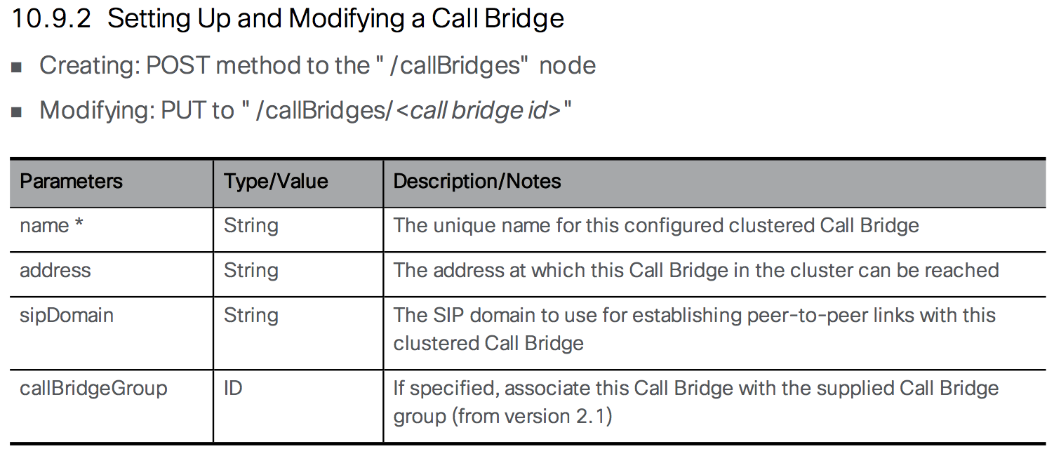
As you can see in the API Reference, you need to modify the /callBridges object and provide a callBridgeGroup. To do this, you need the ID values for both the Call Bridges as well as the ID's for the Call Bridge Groups. To retrieve this data, click to GET /callBridgeGroups and GET /callBridges. You could have used Postman to do these queries as well. Keep these two windows open so you can get the ID values for your queries.
Follow these steps to assign each Call Bridge to a Call Bridge Group. For this lab, we will assign the cms1a and cms1b to the East Call Bridge Group and cms1c to the West Call Bridge Group:
- Switch to Postman and change the verb to PUT
- Construct a URL with the base of https://cms1a.pod2.cms.lab:8443/api/v1/callbridges/ plus the Call Bridge ID for CB_cms1a from GET /callBridges. NOTE: The order of Call Bridges in the list may not be in alphabetical order. Be sure to select the correct ID for cms1a.
- Select the Body tab below the URL
- Ensure that x-www-form-urlencoded is selected
- Switch to Key-Value pairs entry (from Bulk Edit)
- Remove any old key / value rows by clicking X at the right side of each row
- Enter callBridgeGroup as a New key.
- Enter the Call Bridge Group ID for East you got from GET /callBridgeGroups as the value
- Click Send
- Now add cms1b. The URL base stays the same as before: https://cms1a.pod2.cms.lab:8443/api/v1/callbridges/. Change the ID in the URL to the ID of CB_cms1b from GET /callBridges. Remember order of Call Bridges in the list may not be in alphabetical order, so don't just pick the second one on the list assuming it is cms1b. Be sure to select the correct ID for cms1b.
- Since you want this to be in the same Call Bridge Group as cms1a, you can use the same Key / Value pair and just hit Send.
- For CB_cms1c, you must change the URL again so that it now has the Call Bridge ID for CB_cms1c. The URL base stays the same as before: https://cms1a.pod2.cms.lab:8443/api/v1/callbridges/. Change the ID in the URL to the ID of CB_cms1c from GET /callBridges. Remember order of Call Bridges in the list may not be in alphabetical order, so don't just pick the third one on the list assuming it is cms1c. Be sure to select the correct ID for cms1c.
- Replace the Value for callBridgeGroup with the Call Bridge Group ID for West obtained from GET /callBridgeGroups.
- Click Send
Now all the Call Bridges have Call Bridge Group IDs assigned, so they can properly reject calls if the system load limit is exceeded and automatically redirect calls to other servers in the group to keep all calls for a particular space on the same server within the group.
Monitoring Load Balancing
All of these parameters are useful, but how can you monitor the system load? This function is also performed via the API.
- In Postman, change the verb to GET
- Set the URL to https://cms1a.pod2.cms.lab:8443/api/v1/system/load
- Click Send
This API call gives you the current load value for the server to which you sent the request. To see the load across the cluster, you must send individual queries to each server in the cluster. The mediaProcessingLoad value gives you the load that is used to calculate whether or not to reject calls based on the load limit. Currently only the media traffic is monitored and measured, which is what consumes the majority of the CPU resources on the CMS server.
Another way to view the load on a CMS server is to use the Web Admin GUI on each Call Bridge. For example, if you navigate to https://cms1a.pod2.cms.lab:8443 and go to the Status > Calls menu, it will show you all the active calls on that server. Similar to the API, this view only shows you calls active on the server to which you are browsing. There is no way to get a cluster-wide view of calls.
Testing Call Bridge Groups
To test Call Bridge Groups, we will simply repeat our earlier test call, where we place calls from Jabber on the laptop, PC1 and PC2 to pod2user4.space using domains cms1a.pod2.cms.lab, cms1b.pod2.cms.lab, and cms1c.pod2.cms.lab. We expect that calls to CMS1a and CMS1b will be aggregated on one CMS (in the East CallBridge Group) with a distribution call to CMS1c (in the West CallBridge Group).
- Make sure you have Remote Desktop sessions up on PC1 (10.0.102.91) and PC2 (10.0.102.91)
- Using Cisco Jabber on your laptop, click to call our Space at pod2user4@cms1a.pod2.cms.lab
- From PC1's Jabber client, call the same Space, but this time send the call to CMS1B by dialing pod2user4@cms1b.pod2.cms.lab
- From PC2's Jabber client, call the same space, but to CMS1C which is in the West group by dialing pod2user4@cms1c.pod2.cms.lab.
-
You should now see two of the calls on either CMS1A or CMS1B, and the third participant on CMS1C with a
single distribution call between the two servers.:
- CMS1A Active Calls (East Call Bridge Group)
- CMS1B Active Calls (East Call Bridge Group)
- CMS1C Active Calls (West Call Bridge Group)
For example: - When finished, disconnect the remote callers first. Hover over each user in the participant list, right-click and select the Expel option.
-
Once all remote callers have been disconnected, hang up yourself by hovering over the video window and
clicking on the button
SECTION COMPLETE!
You've finished this portion of the lab. We have multiple other optional lab sections, depending on your time and interest, to continue on.
-
Understand other CMS features, such as:
- Spaces, to understand more about how Spaces are organized and configured.
- Ad-hoc conferencing and integration with the Unified CM
- Branding, for a more customized deployment.
-
Explore Cisco Single Edge with Cisco Expressway and CMS:
- Learn about deploying the external WebRTC Web App using Cisco Expressway, to provide external users the same Web Bridge capability.
- Configure advanced Business-to-business calling with Skype for Business gateway calling.
- Investigate a Microsoft on-premise integration example, where you will learn about what is needed to configure a dual-home conferencing experience.
- Experience Cisco Meeting Management (CMM), our free product to allow video conference administrators to provide white-glove conferencing services.
Ad Hoc Conferencing
In traditional Unified CM telephony, ad-hoc conferencing is a call by which two participants are talking directly to one another when one party (using a device registered to the Unified CM) presses the Conference button, calls a different person, and after talking to that 3rd party, presses the Conference button again to join everyone into a 3-party conference. The exact steps may vary depending on the endpoint (e.g. Jabber vs. a physical phone endpoint), but it is always a non-scheduled escalation of a point-to-point call to a multi-party conference.
What makes this feature different than a scheduled or permanent conference is that an adhoc conference is not simply a SIP call to the CMS, as you will see from the configuration on the Unified CM. When the conference initiator presses the Conference button the second time to bring everyone into the same meeting, Unified CM must make an API call to CMS to create a conference on the fly, to which all the calls are then transferred. All this happens transparently to the participants.
This means that Unified CM needs to have the API credentials and Web Admin address/port configured, as well as a SIP trunk directly to the CMS server in in order to extend the call.
When required, CUCM can then dynamically create a Space on CMS, so that each call can be extended directly to CMS and match an Incoming call rule that targets Spaces. Therefore direct SIP trunks to each CMS node in the cluster are required on the Unfied CM. This is required for any Unified CM Integration.
CMS Incoming Call Rules
- Log into the CMS admin for cms1a: https://cms1a.pod2.cms.lab:8443 (Username admin and Password c1sco123)
- Navigate to Configuration > Incoming calls
- Under Call matching, in the Domain name field, enter cms1a.pod2.cms.lab
- For the Priority enter 50.
- Click Add New
- Now add another rule for domain name cms1b.pod2.cms.lab
- Finally, add a rule for domain name cms1c.pod2.cms.lab
You should see:
Note that the domain portion of the Request-URI in the SIP INVITE to a Call Bridge must match one of the configured inbound rules. In this lab, you configured the SIP Trunk Destination on the Unified CM server with the FQDN of the CMS server, cms1a.pod2.cms.lab for the case of cms1a. If the SIP trunk were configured with an IP address, for example, then you would need to add the IP addresses of your CMS servers to the list of domains in the Call matching rules and make sure Target Spaces is set to Yes.
In order to configure the Conference Bridge, a SIP trunk to CMS must exist. We'll configure that first.
SIP Trunk Security Profile
For a secure SIP trunk, you first need to create a SIP Trunk Security Profile that allows for encrypted calls.
- Access the Unified CM at https://cucm1a.pod2.cms.lab/ccmadmin/showHome.do
- Log in with username admin and password c1sco123.
- Navigate to System > Security > SIP Trunk Security Profile
- Click Add New
- Fill in name: Encrypted SIP Trunk Profile for CMS1
- In the Device Security Mode pull-down, choose Encrypted. That should change the Incoming and Outgoing Transport Type to TLS.
- In the X.509 Subject Name field, enter: cms1a.pod2.cms.lab,cms1b.pod2.cms.lab,cms1c.pod2.cms.lab. These are from the SubjectAlternateNames that were specified in the Call Bridge certificates (which you could double-check from the CMS MMP with the pki inspect certname.cer command). We put all of them in there so we can use a single SIP Trunk Security profile on all of the SIP Trunks to each CMS.
- The Incoming Port should be 5061
- Select the Accept replaces header checkbox. CMS can use the REPLACES method in SIP to redirect calls from one CMS to another to optimize usage. This will be discussed in additional detail when we discuss Call Bridge Groups later in the lab.
- Press Save.
SIP Trunk Configuration
Now you can configure the SIP trunks from the UCM cluster to each of the CMS servers.
Add Trunk for CMS1a
- In Unified CM, navigate to Device > Trunk.
- Click Add New
- For Trunk Type, select SIP Trunk
- Click Next
- Configure the following parameters:
Parameter Value Device Name CMS1A-SIP-TRUNK Device Pool Default SRTP Allowed Checked Run On All Active Unified CM Nodes Checked Calling Search Space (under the Inbound Calls section) CSS_INBOUND_CMS
This Calling Search Space is used to limit the calls that can originate from CMS. CMS should be able to call other video endpoints, but should not have PSTN access in this deployment to avoid any potential toll-fraud issues.Calling and Connected Party Info Format Deliver URI and DN in connected party, if available Destination cms1a.pod2.cms.lab
NOTE: You will only configure one destination per trunk. This is because later on, for the ad-hoc conferencing feature, Unified CM needs the ability to send an API message to a specific Call Bridge server and then use a SIP trunk that can only reach that specific server.
Also, if for some reason you see 16 blank lines for entering a destination, this is a browser problem (there should only be 1 shown by default). Use the '-' button to remove the lines 2 through 16 before saving the SIP trunk.Destination Port 5061 SIP Trunk Security Profile Encrypted SIP Trunk Profile for CMS1 Rerouting Calling Search Space CSS_CMS_REROUTING
Note: This parameter is needed for Call Bridge Groups, to be discussed later.SIP Profile LTRCOL-2250 SIP Profile Normalization Script cisco-meeting-server-interop
Note that this is Unified CM 11.5. In older versions of Unified CM, the cisco-meeting-server-interop script did not exist, but could be manually uploaded or you could use the older conductor-interop script that existed in older versions of UCM. - Click Save
- Click OK on the popup
- Click Reset. This step is extremely important for the changes to take effect.
- On the Device Reset popup click Reset
- Click Close
Now you must repeat this configuration to add trunks pointing to cms1b and cms1c. If you would like to do so manually, continue below. If you would like to have these trunks created automatically for you, click HERE to have them added for you automatically. You should see another window pop up with the results. If the addition is successful, you can skip this section and move on to the Adhoc Conference Bridge Configuration for cms1a configuration. If you would like to configure these manually, click the button below to expand the detailed steps.
Add Trunk for CMS1b
- In Unified CM, navigate to Device > Trunk
- Click Add New
- Select SIP Trunk
- Click Next
- Configure the following parameters:
Parameter Value Device Name CMS1B-SIP-TRUNK Device Pool Default SRTP Allowed Checked Run On All Active Unified CM Nodes Checked Calling Search Space CSS_INBOUND_CMS Calling and Connected Party Info Format Deliver URI and DN in connected party, if available Destination cms1b.pod2.cms.lab Destination Port 5061 SIP Trunk Security Profile Encrypted SIP Trunk Profile for CMS1 Rerouting Calling Search Space CSS_CMS_REROUTING SIP Profile LTRCOL-2250 SIP Profile Normalization Script cisco-meeting-server-interop - Click Save
- Click OK on the popup
- Click Reset
- On the Device Reset popup click Reset
- Click Close
Add Trunk for CMS1c
Finally, configure the trunk to cms1c.
- In Unified CM, navigate to Device > Trunk
- Click Add New
- Select SIP Trunk
- Click Next
- Configure the following parameters:
Parameter Value Device Name CMS1C-SIP-TRUNK Device Pool Default SRTP Allowed Checked Run On All Active Unified CM Nodes Checked Calling Search Space CSS_INBOUND_CMS Calling and Connected Party Info Format Deliver URI and DN in connected party, if available Destination cms1c.pod2.cms.lab Destination Port 5061 SIP Trunk Security Profile Encrypted SIP Trunk Profile for CMS1 Rerouting Calling Search Space CSS_CMS_REROUTING SIP Profile LTRCOL-2250 SIP Profile Normalization Script cisco-meeting-server-interop - Click Save
- Click OK on the popup
- Click Reset
- On the Device Reset popup click Reset
- Click Close
You should now have three SIP trunks configured. If you navigate to Device > Trunk in Unified CM Administration and click Find, you should see the trunks go in service as the SIP OPTIONS messages are answered. This can take a couple of minutes. Sometimes the admin page will report that SIP OPTIONS are not enabled until it goes to Full Service.
Adhoc Conference Bridge Configuration for cms1a
Start by configuring a conference bridge resource on the Unified CM cluster pointing to cms1a by following these steps:
- Access the Unified CM at https://cucm1a.pod2.cms.lab
- Log in with username admin and password c1sco123
- Navigate to Media Resources > Conference Bridge
- Click Add New
- For Conference Bridge Type, select Cisco Meeting Server
- In the Conference Bridge Name field, enter CFB_CMS1A
- The Conference Bridge Prefix use a value of
1001.
The Conference Bridge Prefix is a prefix that Unified CM uses when creating the Spaces for adhoc conferences on CMS. The Unified CM will create a randomly generated meeting number for each adhoc conference; however if you have multiple Unified CM clusters using the same CMS for ad-hoc conferences, there's a possibility two clusters could choose the same ID. To ensure this does not happen the value specified in this parameter is prefixed to the randomly generated number and the resulting value is used to generate the meeting ID on CMS.
Best practice is to use a globally unique value for each conference bridge resource you create. Having a unique value also can aid in troubleshooting because it allows you to easily identify which Unified CM cluster created a particular conference when you observe it in CMS. - For the SIP Trunk, choose CMS1A-SIP-TRUNK
By default, this setting determines not just the SIP trunk that will be used to route the SIP calls to CMS, but also the destination for API messages as well. Whatever is configured as the destination address on the SIP trunk will be used as the HTTPS destination for API messages. - Check the Allow Conference Bridge Control of the Call Security Icon. This helps participants know whether or not all participants in a conference are using media encryption.
- The HTTPS Interface Info section allows you to configure the authentication and port information for the API. In the Username field, enter apiadmin
- Set the Password to c1sco123
- Set the Confirm Password to c1sco123
- The HTTPS Port must match the CMS Web Admin listening port, which is
8443
Note: You CANNOT use HTTP for this. All communications must be over HTTPS, which means that the CMS certificates must be loaded on the Unified CM so that Unified CM trusts the certificates presented by CMS. The CMS certificates have already been pre-loaded onto the Unified CM cluster for you. - Click Save
- Click the Reset button
- In the pop-up, click the Reset button again.
- Click the Close button.
If you reload the web page after a few seconds, the status of Conference Bridge device should eventually indicate it is registered. You may have wait up to 30 seconds and reload the page for the status to update.
The registration status only indicates the health of the API connectivity between Unified CM and the CMS server. The status does not have anything to do with the status of the SIP trunk. To become registered, the Unified CM connects to the CMS using the address, port, and credentials supplied. It then sends a GET request to the destination configured on the SIP trunk on the configured port, to check the CMS' system status. For the conference resource you just configured, this would be: https://cms1a.pod2.cms.lab:8443/api/v1/system/status. If you like, you can check this status from your browser using the GET /system/status (username: admin with password: ) request. The results will something like this:
If there is no response, or the Call Bridge isn't active, or any other error is returned, the conference bridge resource will not show as being registered. There is also one other important consideration: Remember that this connection always uses HTTPS. For that reason, the Unified CM MUST trust the certificate, specifically the Web Admin certificate, that the CMS presents when Unified CM connects to it.
Adhoc Conference Bridge Configuration for cms1b
Now you must repeat this configuration to the other two CMS servers as adhoc conference bridge resources. If you would like to do so manually, continue below. If you would like to have these CFB resources created automatically for you, click HERE to have them added for you automatically. You should see another window pop up with the results. If the addition is successful, you can skip this section and move on to the Media Resource Group / List configuration.
Now repeat the same configuration for the other two CMS servers, starting with CMS1B
- Navigate to Media Resources > Conference Bridge
- Click Add New
- For Conference Bridge Type, select Cisco Meeting Server
- In the Conference Bridge Name field, enter CFB_CMS1B
- For Conference Bridge Prefix enter 1002
- For the SIP Trunk, choose CMS1B-SIP-TRUNK
- Check Allow Conference Bridge Control of the Call Security Icon
- In the HTTP Interface Info, for Username enter apiadmin
- Set the Password to c1sco123
- Set the Confirm Password to c1sco123
- Change the HTTPS Port to 8443
- Click Save
- Click the Reset button
- In the pop-up, click the Reset button again.
- Click the Close button.
Adhoc Conference Bridge Configuration for cms1c
Finally, configure the adhoc conference bridge for CMS1C
- Navigate to Media Resources > Conference Bridge
- Click Add New
- For Conference Bridge Type, select Cisco Meeting Server
- In the Conference Bridge Name field, enter CFB_CMS1C
- For Conference Bridge Prefix enter 1003
- For the SIP Trunk, choose CMS1C-SIP-TRUNK
- Check Allow Conference Bridge Control of the Call Security Icon
- In the HTTP Interface Info, for Username enter apiadmin
- Set the Password to c1sco123
- Set the Confirm Password to c1sco123
- The HTTPS Port should be changed to 8443
- Click Save
- Click the Reset button
- In the pop-up, click the Reset button again.
- Click the Close button.
If you go back to Media Resources > Conference Bridge, and click the Find button, you should see that all three conference bridges are registered. If you don't the the last one you just configured registered yet, wait a few seconds and click Find again. Ignore the two devices named CFB_2 and CFB_3. These are software conference resources that are not being used.
Media Resource Group / List
Now that you have configured the Conference Bridge resources, you must configure Unified CM to make them available to users. By default, any device not assigned to a Media Resource Group is available to any user, however it is best practice to assign media resources to a Media Resource Group (MRG) and Media Resource Group List (MRGL) and then use the list to control how those resources are used.
Start by following these steps to add the Media Resource Group:
- In Unified CM, navigate to Media Resources > Media Resource Group
- Click Add New
- In the Name field, enter MRG_CMS1
- In the Available Media Resources box, select CFB_CMS1A, then the down arrow to move it into the Selected Media Resources section.
- Repeat this process to move CFB_CMS1B, into the Selected Media Resources section.
- And finally click on CFB_CMS1C to move it down to the Selected Media Resources
- Click Save
Now that you have created the Media Resource Group, proceed to create the Media Resource Group List by following these steps:
- On Unified CM, navigate to Media Resources > Media Resource Group List
- Click Add New
- In the Name field, enter MRGL_CMS1
- In the Available Media Resource Groups box, select MRG_CMS1, then the down arrow to move it into the Selected Media Resources section.
- Click Save
The last step is to assign the MRGL to devices that are allowed to use it. You could apply this MRGL to a device directly, however in most cases, it is best to assign the MRGL to a Device Pool to make it available to all the devices in the Device Pool. Follow these steps to add the MRGL you created to the Default Device Pool that is being used by your devices.
- On Unified CM, navigate to System > Device Pool
- Click Find
- Click on the Default Device Pool
- On the Media Resource Group List field, select MRGL_CMS1
- Click Save
- The devices must be reset for this change to take effect. Click Reset
- In the pop-up window, click Reset
- Then click Close to close the window
Test Adhoc Conferencing
Now that you have everything configured, you can test making an adhoc conference call. From the Jabber endpoint on your laptop (Pod2 User4), you will place a call to Pod2 User1 by dialing +19195020001. This is a Jabber client on one of your Remote Desktop sessions (PC1). After the call is connected, you will then call Pod2 User2 (Remote Desktop session to PC2) and join the two calls into a conference. There are a few ways to perform this task this in Jabber, but you'll use the way that most closely replicates the sequence you would use on a physical phone endpoint.
- From your laptop's Jabber client, click to call
+19195020001,
which is Pod2 User1.
The call will be auto-answered.

Pod2 User1
Auto-Answers
-
Once the call is active, press the
 button to mute your audio
just to avoid any feedback.
button to mute your audio
just to avoid any feedback.
-
Now press the
 symbol for
additional options, when you hover the mouse over the Jabber call window (Chuck's video)
symbol for
additional options, when you hover the mouse over the Jabber call window (Chuck's video)
-
Next, click the Conference selection
-
Dial Pod2 User2 by pasting
+19195020002
into the Invite Participants search field and then hit enter
-
You now have a direct call between your laptop and User 2 (Amy) while the call to User 1 (Chuck) is
on hold. Join the three calls by clicking on the green
 button and you should be in a meeting with everyone.
-
And now we're in a secure CMS conference with all three participants. From here you can change your layout,
mute and remove remote participants
- When finished, disconnect the remote callers first. Hover over each user in the participant list, right-click and select the Expel option.
-
Once all remote callers have been disconnected, hang up yourself by hovering over the video window and
clicking on the button
SECTION COMPLETE!
You've finished this portion of the lab. We have multiple other optional lab sections, depending on your time and interest, to continue on.
-
Understand other CMS features, such as:
- Spaces, to understand more about how Spaces are organized and configured.
- CallBridge Groups for load balancing calls
- Branding, for a more customized deployment.
-
Explore Cisco Single Edge with Cisco Expressway and CMS:
- Learn about deploying the external WebRTC Web App using Cisco Expressway, to provide external users the same Web Bridge capability.
- Configure advanced Business-to-business calling with Skype for Business gateway calling.
- Investigate a Microsoft on-premise integration example, where you will learn about what is needed to configure a dual-home conferencing experience.
- Experience Cisco Meeting Management (CMM), our free product to allow video conference administrators to provide white-glove conferencing services.
Recording
One optional feature that CMS provides is the ability to record meetings to be viewed later by any or a portion of the attendees. The Recorder service provides the capability to record meetings and save the recordings on a Network File System (NFS) share. The recordings can then be retrieved later for consumption by attendees of a meeting. In addition to using the CMS Recorder service included with CMS, as of version 2.9 there is a new feature allowing recording of CMS meetings using a third-party SIP recording service. For the purposes of this lab, we will be demonstrating how to configure the built-in recording service, but it is important to be aware that the overall strategy for recording CMS meetings is in the process of changing so there are more options available to those administering the CMS environment.
Supported Deployments
CMS is flexible with regard to it's deployment options and may be used in several different ways:
Cisco never recommends having the Call Bridge and Recording services co-resident on a single server due to scalability concerns. With this in mind, the first model recommended by Cisco is the One-to-One model where the Call Bridge services run on one node and the Recorder service runs on a different node. The recorder then sends the recordings to an NFS share on a remote server within the network.
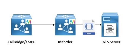
|
The One-to-Many or Redundant Recorder model is another method of deploying the recorder when a resilient recorder is needed. When using this method, recordings are load-balanced between all available Recording nodes. This means that every Call Bridge uses every Recorder node available.
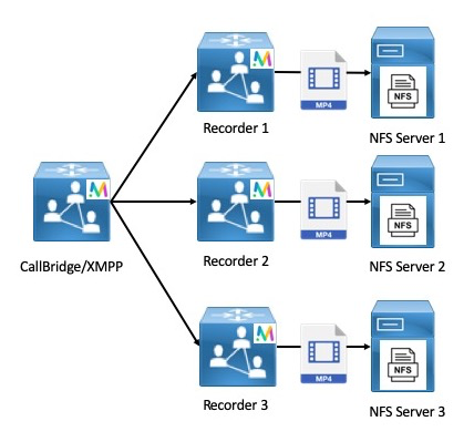
|
This concept of using all available Recorder nodes applies in the opposite direction as well where there are many Call Bridge nodes but only a single Recorder available. While this is supported, it is not necessarily recommended due to the obvious scalability concerns with a model like this.
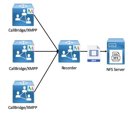
|
As stated earlier, it is not recommended to host the Call Bridge, and Recorder services all on a single CMS node. However, for demo as well as testing purposes it is supported and it is the method we will utilize in this lab to demonstrate the capability of the recorder.
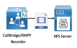
|
XMPP Configuration
The CMS Recorder service acts as an XMPP client, so we need to configure the XMPP server on the Call Bridge being used as the Recorder. We will not concern ourselves with configuring XMPP clustering at this point; the way recording works natively is changing and in future releases it will not rely on the XMPP service, so we want to configure XMPP merely to show how recording is currently achieved, realizing that in future releases the specific configuration will change slightly, doing away with the need for XMPP.
First, let's configure the XMPP service on CMS1a:
| Cisco Meeting Server | Password |
|---|---|
| cms1a.pod2.cms.lab |
- Log into cms1a.pod2.cms.lab (password: ), then copy/paste the following:
xmpp certs cms1a.key cms1a.cer cmslab-root-ca.cer xmpp listen a xmpp domain conf.pod2.cms.lab xmpp enable
-
Next, we need to add the Call Bridges that have permission to connect to the XMPP server so the XMPP service is
aware of them. We will do this one by one:
cms1a> xmpp callbridge add cb-cms1a Success : true Callbridge : cb-cms1a Domain : conf.pod1.cms.lab Secret : zXx7lmXMeWkCmEzvAb1 cms1a> xmpp callbridge add cb-cms1b Success : true Callbridge : cb-cms1b Domain : conf.pod1.cms.lab Secret : PdyagitwSD5OT6PdAb1 cms1a> xmpp callbridge add cb-cms1c Success : true Callbridge : cb-cms1c Domain : conf.pod1.cms.lab Secret : 06y38CkEZCUB5UCaAb1Be sure to note the Call Bridge secret for each call bridge after you add them to the XMPP server. The secrets will be used in the next step below.
- Browse to the cms1a Web Admin page at https://cms1a.pod2.cms.lab:8443
- Enter your credentials (username: admin password: c1sco123) and press Submit
- Navigate to Configuration > General
- For the Unique Call Bridge name, enter cb-cms1a, the value you entered for the Call Bridge in the XMPP configuration in the previous section.
- On the Domain line, enter the XMPP domain, which is conf.pod2.cms.lab
- For Server address, we will enter the hostname of our XMPP server, cms1a.pod2.cms.lab
- Click the [change] link next to the Shared secret box
- In the Shared secret box, you need a copy of the shared secret that was generated on cms1a. You should have noted each shared secret in the steps above, but if not you can connect to the CLI and issue the command to get the shared secrets or click HERE to run a script that will retrieve them for you and display it in a popup web browser window. Copy the secret for cb-cms1a into the Shared secret box.
- Paste the same secret in the Confirm shared secret box
- Scroll down and click Submit
- Now navigate back to the Status > General page to see if the Call Bride service connected to the XMPP service successfully.
-
Repeat the above steps for the remaining Call Bridges by browsing to the Web Admin portal for
cms1b and
cms1c and entering:
- The Unique Call Bridge Name: cb-cms1b and cb-cms1c respectively
- The domain: conf.pod2.cms.lab
- The server address: cms1a.pod2.cms.lab
- The shared secrets for each Call Bridge
After completing the above steps, each Call Bridge should show the XMPP connection as connected. - Launch Postman using the desktop shortcut.
- Change the verb to POST.
- Enter the following URL in the address bar to target the recorders entity: .
- Send an empty POST and you should get back a 200 OK.
- Change the verb to GET and hit Send. You should see output similar to that below with the Recorder ID populated.
- Be sure to save the ID of the Recorder, we'll need it in the next step.
- Change the verb to PUT and set the URL to https://cms1a.pod2.cms.lab:8443/api/v1/recorders/### Your Recorder ID ###
- In the Body, add a key labeled and set the value to
- Hit Send
- We should get a 200 OK.
-
Click Invite Participants
- In the search field enter Pod2 User1
- Now hover over the Pod2 User1 entry and click the green call icon.
-
Click the +E.164 work number for that user to place the outbound call from CMS to the user.
-
This user will auto-answer, as we saw earlier in the lab.
-
Now, you should see the Record button on the Jabber client after clicking the
 button in the call window.
While CMS is recording, you will see the
button in the call window.
While CMS is recording, you will see the
 icon at the top left of your CMS conference window.
-
Wait about 30 seconds to record enough video to play back, then click the
 button after selecting
the button in the call window.
button after selecting
the button in the call window.
- Browse to http://recorder.cms.lab/recordings/?dir=pod2
- You should see a directory listing on the web server we're storing our recordings on. In this directory, CMS creates a subdirectory called spaces which contains subdirectories with a title in the format a long UID which represents the Space ID as CMS defines it.
- You can click on the directory containing your recordings and download the video to test it out.
- Open the video to view the recording you just created.
- When finished, navigate to Jabber to end the call. Disconnect Pod 2 User 1 by hovering over the user in the participant list,
right-clicking and selecting the Expel option. Now, hang up yourself by hovering over the video window and
clicking on the button.
-
Explore Cisco Single Edge with Cisco Expressway and CMS:
- Learn about deploying the external WebRTC Web App using Cisco Expressway, to provide external users the same Web Bridge capability.
- Configure advanced Business-to-business calling with Skype for Business gateway calling.
- Investigate a Microsoft on-premise integration example, where you will learn about what is needed to configure a dual-home conferencing experience.
- Experience Cisco Meeting Management (CMM), our free product to allow video conference administrators to provide white-glove conferencing services.
- The WebAdmin GUI (under Configuration > Spaces) is simple to use, but has very limited options.
- The CMS API has methods to create Spaces individually or in bulk (via a separate API method, using a kind of template to create sequential Spaces).
- Spaces tied to individual users can be constructed using information found in one or more LDAP directories. You have already leveraged this option to create Spaces associated with your imported users.
- In Postman, change the verb to POST
- Make sure the URL field is set to (without the previously deleted coSpace ID): https://cms1a.pod2.cms.lab:8443/api/v1/coSpaces
- Click on the Body tab below the URL.
- If not already selected, select the x-www-form-urlencoded radio button. With this checkbox selected, Postman automatically takes care of encoding the information for you. Alternatively, you could pick the Raw format and encode the information manually using something like https://www.freeformatter.com/url-encoder.html. One of the advantages of Postman is its ability to do this all for you.
- Although based on the API documentation above there are no required parameters, you will enter
the following:
Parameter / Key Value name LTRCOL-2250 uri pod2 Instead of entering these key/value pairs separately, you can toggle to Bulk Edit mode so you can now enter them all at once by pasting the following into the Bulk Edit window:
name:LTRCOL-2250 uri:pod2 - Click Send. Your inputs and the result should look like this:
- Now place a call to pod2@conf.pod2.cms.lab to confirm functionality.
- In Postman, change the verb to POST.
- Change the URL field to https://cms1a.pod2.cms.lab:8443/api/v1/callLegProfiles
- Click on the Body tab below the URL.
- Make sure the x-www-form-urlencoded option is checked.
- If necessary, switch click Bulk Edit at the right to switch to that entry mode. Clear out any old data in the entry window.
- Create the Host callLegProfile using the Bulk Edit settings at right:
Parameter / Key Value Description needsActivation false This callLegProfile will allow the caller to contribute audio and video. I.e. they are a "full/activator” participant defaultLayout speakerOnly speakerOnly is a full screen layout of only the host presentationContributionAllowed true Allowed to share content rxAudioMute false Allowed to send audio. Whether to block receiving audio from this call leg rxVideoMute false Allowed to send video Instead of entering these key/value pairs, you should toggle to Bulk Edit mode and enter them all at once by pasting the following into the Bulk Edit window:
needsActivation:false defaultLayout:speakerOnly presentationContributionAllowed:true rxAudioMute:false rxVideoMute:false -
Press Send
- Create the Guest callLegProfile using the Bulk Edit settings at right:
Parameter / Key Value Description needsActivation true This callLegProfile requires a "full/activator” participant (i.e. a host) to join first defaultLayout speakerOnly speakerOnly is a full screen layout of only the host presentationContributionAllowed false Not allowed to share content rxAudioMute true Block receiving audio from this call leg rxVideoMute false Allowed to send video deactivationMode deactivate What to do when the last "activator" (host) leaves. In this case, participants will be removed from the meeting. Instead of entering these key/value pairs, you should toggle to Bulk Edit mode and enter them all at once by pasting the following into the Bulk Edit window:
needsActivation:true defaultLayout:speakerOnly presentationContributionAllowed:false rxAudioMute:true rxVideoMute:false deactivationMode:deactivate -
Press Send
-
Next associate the Guest callLegProfile with the created coSpace. To do this, you will need both the the ID of
the coSpace created previously as well as the ID of the Host callLegProfile.
GET /coSpaces from the browser.
- In Postman, change the method from POST to PUT, since this will be a modification of an existing object.
- Change the URL to https://cms1a.pod2.cms.lab:8443/api/v1/coSpaces/###COSPACE ID for LTRCOL-2250###
- In the Body tab, make sure x-www-form-urlencoded is selected.
- Ensure Bulk Edit mode is selected and overwrite anything in the Body window with
- Press Send
-
Finally, create the Host accessMethod on the same Space.
- In Postman, change the method from PUT to POST
- Append /accessMethods to the URL, so that it reads https://cms1a.pod2.cms.lab:8443/api/v1/coSpaces/###COSPACE_ID###/accessMethods
- In the Body tab, make sure x-www-form-urlencoded is selected.
-
Ensure Bulk Edit mode is selected and overwrite anything in the Body window with
uri:host callLegProfile:###HOST_CALL_LEG_PROFILE### (The one with needsActivation set to False) passcode:111
- Press Send
- Now place a call to pod2@conf.pod2.cms.lab from both PC1 and PC2 to join as a guest. You'll hear the "Waiting for your host to join" prompt.
- Then place a call to host@conf.pod2.cms.lab to join as the host.
-
When prompted hover over the Jabber video window, click the
 icon and enter 111#. The other participants are immediately joined to the meeting and are muted.
- When finished, remove the remote participants and hang up the call.
-
Understand other CMS features, such as:
- Ad-hoc conferencing and integration with the Unified CM
- CallBridge Groups for load balancing calls
- Branding, for a more customized deployment.
-
Explore Cisco Single Edge with Cisco Expressway and CMS:
- Learn about deploying the external WebRTC Web App using Cisco Expressway, to provide external users the same Web Bridge capability.
- Configure advanced Business-to-business calling with Skype for Business gateway calling.
- Investigate a Microsoft on-premise integration example, where you will learn about what is needed to configure a dual-home conferencing experience.
- Experience Cisco Meeting Management (CMM), our free product to allow video conference administrators to provide white-glove conferencing services.
- Enable MRA
- Configure Cisco Meeting Server
- UC Client Traversal Zone
- Expressway-C Certificates
- Open the browser to the Expressway-C at https://expc1a.pod2.cms.lab
- Log in with username admin and password c1sco123.
- If prompted, click Skip Service Setup Wizard
- Navigate to Configuration > Unified Communications > Configuration
- For Unified Communications mode select Mobile and remote access
- For Authorize by OAuth token with refresh select Off
- Click Save. Other options to specify the Authentication path and Single sign-on options are not needed for our lab deployment.
- Navigate to Configuration > Unified Communications > Cisco Meeting Server
- Change Meeting Server Web Proxy to Enable
-
For Guest account client URI, enter the URI that users use to access the CMS Web Bridge,
join.pod2.cms.lab.
Note: If your deployment was using a non-standard port for Web Bridge (i.e. not 443), this interface does not allow you to specify a port. The only way to use a non-standard port is to use DNS SRV records. Expressway will query for an SRV record for the domain,_cms-web._tls.domain , which will return a hostname and a port. Because you are using a the standard port number, this is not necessary. - Click Save
- Navigate to Configuration > Zones > Zones.
- Click New
- Enter in the Name field
- For the Type, select Unified Communications traversal
- In the Username field enter the user you created earlier on the Expressway-E.
- In the Password field enter If pasting this value, use Control-V
- For the SIP Port, enter
- In the Location section, for Peer 1 address enter the FQDN of the Expressway-E, . If the Expressway-E were a cluster, all other members would be explicitly listed on separate peer addresses.
- Click Create Zone
- Enable MRA to allow Web Proxy on Expressway-E
- Change Expressway-E Web Administration port
- Configure the UC Traversal server on the Expressway-E to tunnel signaling through the corporate firewall
- Create certificate for the Expressway-E
- On the Expressway-C, enable MRA
- Configure the UC Traversal client on the Expressway-C
- Configure CMS servers on Expressway-C
- Create certificate for the Expressway-C
- Enable the Expressway-E TURN service for media traversal
- Open the browser to the Expressway-E at https://expe1a.pod2.cms.lab
- Log in with username admin and password c1sco123.
- If prompted, click Skip Service Setup Wizard
- Navigate to Configuration > Unified Communications > Configuration
- For Unified Communications mode select Mobile and remote access
- Click Save
- Navigate to System > Administration on Expressway-E at https://expe1a.pod2.cms.lab
- Near the bottom, find the Web administrator port setting and change it to 445
- Click Save
- You should see a message near the top of the screen that indicates System settings have been saved, however a restart is required for them to take effect. Don't bother with this now. You'll restart the server later on. Just keep in mind, the next time the system is restarted, you'll need to point the browser to port 445.
- Navigate to Configuration > Authentication > Devices > Local database.
- You should see that a user, traversal has already been configured. This was used for the traditional Traversal Zone for Business to Business communication
- Click New
- Enter in the Name field.
- In the Password field enter . If pasting this value, use Control-V. Do NOT right-click and select Paste. Failure to do this properly will result in failures later in the lab.
- Click Create credential
- Navigate to Configuration > Zones > Zones.
- Click New
- Enter in the Name field.
- For the Type, select Unified Communications traversal.
- In the Username field enter , the user created in the previous section.
- For the SIP Port, enter
.
Note: For this lab you will use port 7001 for the UC Traversal Zone because the Traversal Zone set up for you is using 7002. In a real environment, the port usage would depend entirely on what was already set up. You must use an unused port for this zone. - In the TLS verify subject name, enter , the Common Name of the Expressway-C's certificate which will be presented to the Expressway-E to create a secure connection between the two servers.
- Click Create Zone
- Navigate to Maintenance > Security > Server certificate
- In the Server certificate data section, next to Server certificate, click Show (decoded)
- If you scroll down in this certificate, you'll reach a section where it displays the X509v3 Subject Alternate Name, which will show DNS:expe1a.pod2.cms.lab, which is the host name of the Expressway-E and the DNS:join.pod2.cms.lab, which is the URL that external users will enter on their browser to access Web Bridge. The CMS have this last hostname in its own certificate, as well as the Expressway-E.
- Now that everything has been verified, reboot the Expressway-E. Navigate to Maintenance > Restart options, click Restart and Ok to confirm.
- Open the browser to the Expressway-E at https://expe1a.pod2.cms.lab:445
- Log in with username admin and password c1sco123
- Navigate to Configuration > Authentication > Devices > Local database
- Click New
- Enter in the Name field
- In the Password field enter - If pasting this value, use Control-V
- Click Create credential
- Navigate to Configuration > Traversal > TURN
- For TURN services, select On
-
For TCP 443 TURN service select On.
This is an Expressway X8.11 and later feature that allows the external clients to use port 443 to access the TURN server. This helps avoid issues where external clients are on networks where traffic to the default TURN port, 3478, is being blocked. - In the Authentication realm line, enter
- Click Save Notice in the TURN server status for the 10.0.132.X external addresses that it is now listening on port 3478 and port 443.
- The system warns you that this change requires a restart, click on the restart text (or navigate to Maintenance > Restart options and click Restart
- Click OK to confirm the restart.
- Launch or switch to the Postman app
- Switch to the POST verb.
- Put in the following URL: https://cms1a.pod2.cms.lab:8443/api/v1/turnServers
- From the Body tab, make sure the x-www-form-urlencoded radio button is selected.
-
You may enter the parameters either using Key-Value or Bulk Edit mode.
Bulk Edit is definitely quicker. In either case, remove any other old parameters.
Enter each Key / Value pair as noted in the table below. The table outlines the decisions that were made in choosing these values.
Parameter / Key Value serverAddress 10.0.102.71
Description: The IP address that CMS should expect to get traffic from when invoking this TURN server.clientAddress 10.0.132.102
Description: The address that clients should send traffic to in order to reach this TURN server. This is the external address of the TURN server.username
Description: The TURN server username configured on the Expressway-Epassword c1sco123
Description: The password associated with the TURN server user on the Expressway-Etype expressway The following is the same data in the format that can be pasted into the Bulk Edit window.
serverAddress:10.0.102.71 clientAddress:10.0.132.102 username:turnuser password:c1sco123 type:expressway - Click Send in Postman.
- In Postman switch to the GET verb. Leave the URL unchanged from the POST request you just sent.
- Press Send
- The results gives you some basic information about the TURN server and also includes the turnServer ID.
- Copy the turnServer ID value from the result above and append it to the existing URL to query the object. The resulting URL should look something like https://cms1a.pod2.cms.lab:8443/api/v1/turnServers/abb5ecf5-e2b6-48f4-a60b-0ef3eaa99ec2
- Press Send again.
-
Now you can see all the settings you just configured. If you want to get some runtime status information
for the TURN server, append /status to the end of the URL. The URL should look something
like
https://cms1a.pod2.cms.lab:8443/api/v1/turnServers/abb5ecf5-e2b6-48f4-a60b-0ef3eaa99ec2/status - Press Send again.
- This API call provides some useful information. Note that reachable is true, along with the roundTripTimeMs. If your Expressway-E/TURN server is not yet up, then this command will likely show different results, indicating that it is not reachable.
- If not already connected, launch a Remote Desktop Protocol session to PC3 by clicking on the PC3 shortcut on your laptop's Desktop. (If necessary, log in with username admin and password c1sco123
- On this machine, launch Chrome, which should be a big icon on the Desktop.
-
Enter the Web Bridge URL, https://join.pod2.cms.lab.
Note: This may be the default Chrome home page for some clients. -
When the page loads you should see both Join call and Sign in options.
The fact that you can see this page confirms that Web Proxy is working. To verify that TURN is working,
Click Sign in
- Enter the username pod2user3@conf.pod2.cms.lab and password c1sco123 then click Sign In
-
Now, with Pod2 User3's Space highlighted, click on
the Join meeting button
- If you are prompted to allow access to the camera and microphone, click Allow.
-
From Jabber on your laptop, join this same conference. Just place a call to
pod2user3.space@conf.pod2.cms.lab
-
With the call up, one way to verify that the TURN server is in use is by looking at the Expressway-E, the TURN server itself.
Open a browser to the Expressway-E at https://expe1a.pod2.cms.lab:445 - Log in with username admin and password c1sco123
- Navigate to Status > TURN relay usage
-
You should see two active TURN clients. These are the session between CMS (which could be either
10.0.102.51, 10.0.102.52, or 10.0.102.53) and the TURN server, and the WebRTC client on PC3, which has the IP address 10.0.132.52.
-
In the web browser on PC3, click the red
 disconnect
button to in the CMA browser, and close the browser. On Expressway, you should see the TURN relay released.
disconnect
button to in the CMA browser, and close the browser. On Expressway, you should see the TURN relay released.
- Hang up the call from Jabber, as well.
-
Understand other CMS features, such as:
- Spaces, to understand more about how Spaces are organized and configured.
- Ad-hoc conferencing and integration with the Unified CM
- CallBridge Groups for load balancing calls
- Branding, for a more customized deployment.
-
Explore Cisco Single Edge with Cisco Expressway and CMS:
- Configure advanced Business-to-business calling with Skype for Business gateway calling.
- Investigate a Microsoft on-premise integration example, where you will learn about what is needed to configure a dual-home conferencing experience.
- Experience Cisco Meeting Management (CMM), our free product to allow video conference administrators to provide white-glove conferencing services.
- Log in to the Expressway-C at https://expc1a.pod2.cms.lab (username: admin and password: c1sco123)
- Navigate to Configuration > Dial plan > Search rules.
- Click New
- Create a Search Rule with the following:
Parameter Value Rule Name Priority 150 Protocol SIP Mode Alias pattern match Pattern type Regex Pattern string
Note: Notice this is the same as the DNS zone on the Expressway-E.Pattern behavior Leave On successful match Continue
Note: Having this parameter set to Continue allows Expressway to keep searching for possible matches if there is a failure on this rule. We will show a use case for this later on when CMS is used to convert different SIP variants.Target Traversal Zone
- Open the browser to the Expressway-E at
https://expe1a.pod2.cms.lab:445
Note: If you skipped the External WebRTC section, then you'll need to use https://expe1a.pod2.cms.lab, as the admin port has not yet been changed. - Log in with username admin and password c1sco123
- Navigate to Configuration > Dial plan > Search rules
- Click New
- Configure the following:
Parameter Value Rule Name Priority 10
Note: Remember that the lower the number the higher the priority in the Expressway productProtocol SIP Mode Alias pattern match Pattern type Regex Pattern string
Note: This regular expression matches any URI that is either the Jabber / Unified CM domain, pod2.cms.lab or the CMS domain, conf.pod2.cms.lab. The Expressway has good regular expression support. There is also a tool within the GUI, under Maintenance > Tools > Check pattern that allows you to test your expressions and has links to the relevant help sections.Pattern behavior Leave On successful match Stop Target Traversal Zone
- Click Create search rule.
- Navigate to Configuration > Dial plan > Search rules.
- Click New
- Configure the following:
Parameter Value Rule Name Priority 20 Protocol SIP Source Named Source name Traversal Zone
Note: This is to limit this rule to requests coming from the inside/traversal zone. This avoids routing loops.Mode Alias pattern match Pattern type Regex Pattern string
Note: Notice this is the previous regular expression, enclosed in a negation to indicate a match of anything that is NOT the old expression (?! old expression).Pattern behavior Leave On successful match Stop Target DNS Zone
- Click Create search rule.
-
External Skype for Business caller (skype2@ms.com) calls a
standards-based user on the UC domain (pod2user4@pod2.cms.lab). For this call flow:
- The Expressway-E will recognize the UC domain and route it via the Traversal Zone to the Expressway-C.
- From there, the Expressway-C will have a search rule for the MSSIP calls to the UC domain to route to CMS.
- CMS will have a forwarding rule for the UC domain as well as an outbound rule for the same domain, routing the call back to the Expressway-C as a standards-based SIP call.
- Expressway-C now routes the standards-based SIP call to the UC domain to CUCM where the endpoint can answer the call.
-
Standards-based user on the UC domain (pod2user4@pod2.cms.lab) calls an external
Skype for Business user (skype2@ms.com. This is the call flow in the case of an open federation:
- The Unified CM, just like any other B2B call, will route the call to the Expressway-C.
- Similarly, Expressway-C routes the call to Expressway-E
- Expressway-E will attempt to use its DNS Zone by querying for standards-based public DNS SRV records. These will fail and a 404 Not Found will be returned to Expressway-C
- Expressway-C will now Continue to route the call to CMS
- CMS will have a forwarding rule for all domains, as well as an outbound rule for all domains as a Lync-type call back to Expressway-C
- Expressway-C, just as with the original call, will route the call outbound to the Expressway-E
- The Expressway-E will again use its DNS zone, but given the presence of Microsoft SIP variants, will perform DNS queries for the Microsoft SRV records (_sipfederationtls._tcp.ms.com). This will succeed and the call can complete
- Log in to the Expressway-C at https://expc1a.pod2.cms.lab (username: admin and password: c1sco123)
- Navigate to Configuration > Dial plan > Search rules on Expresssway-C. Click New
- Configure the following:
Parameter Value Rule Name Priority 100 Protocol SIP SIP Variant Microsoft AV & Share Source Any Mode Alias pattern match Pattern type Regex Pattern string Pattern behavior Leave On successful match Continue Target CMS1a Zone - Click Create search rule.
- Find the rule just created called UC domain MSSIP to CMS1a and at the right of that row, click Clone.
- Change the Rule Name to
- Change the Priority to 101
- Change the Target to CMS1b Zone
- Click Create search rule.
- Find the rule just created called UC domain MSSIP to CMS1b and at the right of that row, click Clone.
- Change the Rule Name to
- Change the Priority to 102
- Change the Target to CMS1c Zone
- Change the On successful match setting to Stop
- Click Create search rule.
- Log in to the Expressway-C at https://expc1a.pod2.cms.lab (username: admin and password: c1sco123)
- Navigate to Configuration > Dial plan > Search rules.
- Click New
-
Configure the following:
Parameter Value Rule Name Priority 151 Protocol SIP SIP Variant Standards-Based Mode Alias pattern match Pattern type Regex Pattern string Pattern behavior Leave On successful match Continue Target CMS1a Zone
- Click Create search rule.
- Find the rule just created called Non-Local domains to CMS1a and at the right of that row, click Clone.
- Change the Rule Name to
- Change the Priority to 152
- Change the Target to CMS1b Zone
- Click Create search rule.
- Find the rule just created called Non-Local domains to CMS1b and at the right of that row, click Clone.
- Change the Rule Name to Non-Local domains to CMS1c
- Change the Priority to 153
- Change the On successful match setting to Stop
- Change the Target to CMS1c Zone
- Click Create search rule.
- Log in to the Expressway-C at https://expc1a.pod2.cms.lab (username: admin and password: c1sco123)
- Navigate to Configuration > Dial plan > Search rules.
- Click New
-
Configure the following:
Parameter Value Rule Name Priority 140 Protocol SIP Source Named Source name CMS1a Zone Mode Alias pattern match Pattern type Regex Pattern string (?!.*@(conf\.)?pod2\.cms\.lab).* Pattern behavior Leave On successful match Stop Target Traversal Zone
- Click Create search rule.
- Find the rule just created called Outbound Zone from CMS1a and at the right of that row, click Clone.
- Change the Rule Name to
- Change the Source name to CMS1b Zone
- Click Create search rule.
- Find the rule just created called Outbound Zone from CMS1b and at the right of that row, click Clone.
- Change the Rule Name to
- Change the Source name to CMS1c Zone
- Click Create search rule.
- Access CMS admin for the CMS: https://cms1a.pod2.cms.lab:8443/
- Navigate to Configuration > Incoming calls
- Add a rule for the local UC domain:
- Under Call forwarding, in the first blank row, under Domain matching pattern, enter
- Set the Priority to 1
- Change the Forward setting to forward
- Set the Caller ID setting to pass through, because we want these to be completely unchanged for anything that's not a Microsoft destination.
- Click Add New
- Add a default rule for unknown destinations:
- Under Domain matching pattern, enter
- Set the Priority to 0
- Change the Forward setting to forward
- Set the Caller ID setting to use dial plan. This will cause the From portion to be overwritten later in the Outbound rules, which is needed for Lync/Skype destinations when using a CMS cluster. As a rule of thumb, when forwarding Skype calls, select use dial plan, otherwise select passthrough.
- Click Add New
- Launch Postman and change the verb type to POST
- Change the URL field to https://cms1a.pod2.cms.lab:8443/api/v1/outboundDialPlanRules
- Click on the Body tab below the URL.
- If not already selected, select the x-www-form-urlencoded radio button.
- Remove any previously configured parameters
- We'll list the necessary parameters, however it is strongly recommended to use Bulk Edit entry
mode (using the right column):
Parameter / Key Value domain Left blank, which defaults to "<match all domains>" sipProxy expc1a.pod2.cms.lab trunkType lync failureAction continue
There will now be multiple default routes, the first will try Lync, the last will try standards-based, which is necessary for numeric dialing from CMS.priority 2 sipControlEncryption encrypted
Skype/Lync trunks must always be fully encryptedlocalContactDomain
This will enable the remote clients to be able to call back or share with the call.cms1a.pod2.cms.lab localFromDomain
This will make the call as it arrives at the remote end appear as originating from the UC domain.pod2.cms.lab scope callBridge callbridge This will be the callBridge ID value for CB_cms1a obtained from the GET /callBridges Paste the following into the Bulk Edit window:
domain: sipProxy:expc1a.pod2.cms.lab trunkType:lync failureAction:continue priority:2 sipControlEncryption:encrypted localContactDomain:cms1a.pod2.cms.lab localFromDomain:pod2.cms.lab scope:callBridge callbridge:###_Replace_with_CMS1a_callBridge_ID_### - Click Send. Your inputs and the result should look like this (with a different
callBridge ID):
- Of course, we need to repeat this with CMS1b and CMS1c. We can use the previous POST message. In the Bulk Edit portion, simply replace the localContactDomain line with: localContactDomain:cms1b.pod2.cms.lab and on the callbridge line, replace the callBridgeID with that of the callBridgeID of CB_cms1b (obtained from GET /callBridges
- Hit Send
- Finally we repeat the steps for CMS1c. Use the previous POST. In the Bulk Edit portion, replace the localContactDomain line with: localContactDomain:cms1c.pod2.cms.lab and on the callbridge line, replace the callBridgeID with that of the callBridgeID of CB_cms1c (from GET /callBridges)
- Click Send
- A call from both the Skype and Jabber users directly into a Space.
- A direct URI call (gateway call) from Jabber to an external Skype user
- A direct URI call (gateway call) from a Skype user to Jabber
- Access PC3, your "outside" client. Make sure Chrome is quit
- Open up the Skype for Business client. In the FAVORITES folder, find the pod2user4.space@conf.pod2.cms.lab Contact
- Right-click on the contact
- Click Start a Video Call. The call will be auto-answered and you will be in User4's meeting Space
- From Jabber on your laptop, dial pod2user4.space@conf.pod2.cms.lab
- Disconnect the previous call.
- On PC3, in the FAVORITES folder of the Skype for Business client, find the pod2user4@pod2.cms.lab
- Right-click on the contact
- Click Start a Video Call
- On your laptop, answer the call on Jabber
-
Understand other CMS features, such as:
- Spaces, to understand more about how Spaces are organized and configured.
- Ad-hoc conferencing and integration with the Unified CM
- CallBridge Groups for load balancing calls
- Branding, for a more customized deployment.
-
Explore Cisco Single Edge with Cisco Expressway and CMS:
- Learn about deploying external WebRTC Web App using Cisco Expressway, to provide external users the same Web Bridge capability.
- Investigate a Microsoft on-premise integration example, where you will learn about what is needed to configure a dual-home conferencing experience.
- Experience Cisco Meeting Management (CMM), our free product to allow video conference administrators to provide white-glove conferencing services.
- Open the browser to the Expressway-E at https://expe1a.pod2.cms.lab:445
- Log in with username admin and password c1sco123
- Navigate to Configuration > Authentication > Devices > Local database
- Click New
- Enter in the Name field
- In the Password field enter - If pasting this value, use Control-V
- Click Create credential
- Navigate to System > Administration on Expressway-E at https://expe1a.pod2.cms.lab
- Near the bottom, find the Web administrator port setting and change it to 445
- Click Save
- You should see a message near the top of the screen that indicates System settings have been saved, however a restart is required for them to take effect. Don't bother with this now. You'll restart the server later on. Just keep in mind, the next time the system is restarted, you'll need to point the browser to port 445.
- Navigate to Configuration > Traversal > TURN
- For TURN services, select On
-
For TCP 443 TURN service select On.
This is an Expressway X8.11 feature that allows the external clients to use port 443 to access the TURN server. This helps avoid issues where external clients are on networks where traffic to the default TURN port, 3478, is being blocked. - In the Authentication realm line, enter
- Click Save
Notice in the TURN server status for the 10.0.132.X external addresses that it is now listening on port 3478 and port 443.
- The system warns you that this change requires a restart, click on the restart text (or navigate to Maintenance > Restart options and click Restart
- Click OK to confirm the restart.
- Launch or switch to the Postman app
- Switch to the POST verb.
- Put in the following URL: https://cms1a.pod2.cms.lab:8443/api/v1/turnServers
- From the Body tab, make sure the x-www-form-urlencoded radio button is selected.
- This is another excellent place to use the Bulk Edit mode, so click on the Bulk Edit text in the row under the x-www-form-urlencoded button.
- Enter each Key / Value pair as noted in the table below. The table outlines the decisions that were made in
choosing these values.
The following is the same data in the format that can be pasted into the Bulk Edit window.Parameter / Key Value serverAddress 10.0.102.71
Description: The IP address that CMS should expect to get traffic from when invoking this TURN server.clientAddress 10.0.132.102
Description: The address that clients should send traffic to in order to reach this TURN server. This is the external address of the TURN server.username
Description: The TURN server username configured on the Expressway-Epassword c1sco123
Description: The password associated with the TURN server user on the Expressway-Etype expressway
serverAddress:10.0.102.71 clientAddress:10.0.132.102 username:turnuser password:c1sco123 type:expressway - Click Send in Postman.
- In Postman switch to the GET verb. Leave the URL unchanged from the POST request you just sent.
-
Press Send
- The results gives you some basic information about the TURN server and also includes the turnServer ID.
- Copy the turnServer ID value from the result above and append it to the existing URL to query the object. The resulting URL should look something like https://cms1a.pod2.cms.lab:8443/api/v1/turnServers/abb5ecf5-e2b6-48f4-a60b-0ef3eaa99ec2
- Press Send again.
-
Now you can see all the settings you just configured. If you want to get some runtime status information
for the TURN server, append /status to the end of the URL. The URL should look something
like
https://cms1a.pod2.cms.lab:8443/api/v1/turnServers/abb5ecf5-e2b6-48f4-a60b-0ef3eaa99ec2/status - Press Send again.
- This API call provides some useful information. Note that reachable is true, along with the roundTripTimeMs. If your Expressway-E/TURN server is not yet up, then this command will likely show different results, indicating that it is not reachable.
- pod2.cms.lab - the Unified CM domain (i.e. all Jabber endpoints have this as their host portion)
- conf.pod2.cms.lab - the CMS domain, containing all user's CMS Spaces
- s4b.cms.lab - the Skype for Business domain
- Log in to the Expressway-C at https://expc1a.pod2.cms.lab (username: admin and password: c1sco123)
- Navigate to Configuration > Dial plan > Search rules and click New
- Configure the following to route MSSIP traffic to the S4B Zone:
Parameter Value Rule Name Priority 100 Protocol SIP SIP Variant Microsoft Variants Source Any Mode Alias pattern match Pattern type Regex Pattern string Pattern behavior Leave On successful match Stop Target S4B Zone - Click Create search rule.
- Navigate to Configuration > Dial plan > Search rules on Expresssway-C. Click New
- Configure the following:
Parameter Value Rule Name Priority 100 Protocol SIP SIP Variant Standards-based Source Any Mode Alias pattern match Pattern type Regex Pattern string Pattern behavior Leave On successful match Continue Target CMS1a Zone - Click Create search rule.
- Find the rule just created called S4B domain StdSIP to CMS1a and at the right of the row, click Clone.
- Change the Rule Name to S4B domain StdSIP to CMS1b
- Change the Priority to 101
- Change the Target to CMS1b Zone
- Click Create search rule.
- Find the rule just created called S4B domain StdSIP to CMS1b and at the right of the row, click Clone.
- Change the Rule Name to S4B domain StdSIP to CMS1c
- Change the Priority to 102
- Change the On successful match to Stop
- Change the Target to CMS1c Zone
- Click Create search rule.
- Log in to the Expressway-C at https://expc1a.pod2.cms.lab (username: admin and password: c1sco123)
- Navigate to Configuration > Dial plan > Search rules on Expresssway-C. Click New
- Configure the following:
Parameter Value Rule Name Priority 100 Protocol SIP SIP Variant Microsoft AV & Share Source Any Mode Alias pattern match Pattern type Regex Pattern string Pattern behavior Leave On successful match Continue Target CMS1a Zone - Click Create search rule.
- Find the rule just created called UC domain MSSIP to CMS1a and at the right of that row, click Clone.
- Change the Rule Name to
- Change the Priority to 101
- Change the Target to CMS1b Zone
- Click Create search rule.
- Find the rule just created called UC domain MSSIP to CMS1b and at the right of that row, click Clone.
- Change the Rule Name to
- Change the Priority to 102
- Change the Target to CMS1c Zone
- Change the On successful match setting to Stop
- Click Create search rule.
- Access CMS admin for CMS1a: https://cms1a.pod2.cms.lab:8443/incoming_calls.html.
- Navigate to Configuration > Incoming calls
- Add a rule for the local UC domain. This rule may already be present if you configured the Expressway Edge section:
- Under Call forwarding, in the first blank row, under Domain matching pattern, enter
- Set the Priority to 1
- Change the Forward setting to forward
- Set the Caller ID setting to pass through, because we want these to be completely unchanged for anything that's not a Microsoft destination.
- Click Add New
- Add a default rule for the Skype for business domain:
- Under Domain matching pattern, enter s4b.cms.lab
- Set the Priority to 1
- Change the Forward setting to forward
- Set the Caller ID setting to pass through
- Click Add New
- Launch Postman
- Specify the POST verb, in order to add a new rule.
- Change the URL to https://cms1a.pod2.cms.lab:8443/api/v1/OutboundDialPlanRules
- Click on the Body tab below the URL.
- If not already selected, select the x-www-form-urlencoded radio button.
- If necessary, click on the Bulk Edit selection at the right of the Key/Value headers, then get rid of any old data.
-
The following parameters need to be configured, listed here as shown in the GUI as well as the corresponding
API parameter:
GUI Parameter API Parameter Value Domain domain s4b.cms.lab
Our Skype for Business domain.SIP proxy to use sipProxy expc1a.pod2.cms.lab Local contact domain localContactDomain cms1a.pod2.cms.lab
The CMS1a FQDN.Trunk type trunkType Lync Behavior failureAction Stop Priority priority 90 Encryption sipControlEncryption Encrypted Call Bridge Scope scope callBridge Call Bridge Scope callbridge ###_CB_cms1a_callBridge_ID_### In Postman, the following parameter pairs can be pasted in to the bulk entry window:
domain:s4b.cms.lab sipProxy:expc1a.pod2.cms.lab localContactDomain:cms1a.pod2.cms.lab trunkType:lync failureAction:Stop priority:90 sipControlEncryption:encrypted scope:callBridge callbridge:###_CB_cms1a_callBridge_ID_### -
Click Send
-
You only need to repeat this for cms1b and cms1c, changing only the
localContactDomain parameter. For cms1b
paste the following into the Postman bulk edit window and click Send:
domain:s4b.cms.lab sipProxy:expc1a.pod2.cms.lab localContactDomain:cms1b.pod2.cms.lab trunkType:lync failureAction:Stop priority:90 sipControlEncryption:encrypted scope:callBridge callbridge:###_CB_cms1b_callBridge_ID_###
- Lastly, for cms1c paste this into the bulk edit window of Postman and click Send:
domain:s4b.cms.lab sipProxy:expc1a.pod2.cms.lab localContactDomain:cms1c.pod2.cms.lab trunkType:lync failureAction:Stop priority:90 sipControlEncryption:encrypted scope:callBridge callbridge:###_CB_cms1c_callBridge_ID_###
- Examine the Outbound rules from the CMS GUI. Log in to https://cms1a.pod2.cms.lab:8443/outbound_calls.html (Username: admin, Password: c1sco123)
-
You should see the three new rules that have been created in addition to the first two you already had. Make
sure the Local contact domain entry is for the same server specified in the
Call Bridge Scope
- Navigate to Configuration > Incoming Calls, or https://cms1a.pod2.cms.lab:8443/incoming_calls.html.
- Add a domain with the following parameters in the Call matching section:
As performed earlier, you could have sent a POST to the /inboundDialPlanRules node.GUI Parameter API Parameter Value Domain name domain s4b.cms.lab Priority priority 40 Targets spaces resolveTocoSpaces No Targets users resolveToUsers No Targets IVRs resolveToIvrs No Targets Lync resolveToLyncConferences Yes - Click Add New
- First, CMS1a:
- Navigate to Configuration > General, or https://cms1a.pod2.cms.lab:8443/config.html (Username: admin, Password: c1sco123)
- In the Lync Edge settings section, for Server address, enter s4b-fe.cms.lab
- Below that line, for Username, enter pod1cms2aedge@s4b.cms.lab
- For Number of registrations, enter 3
- At the bottom of the page, click Submit
-
Now check to see if things are properly registered. Navigate to
Status > General and observe that the
Lync Edge registrations should show "3 configured, 3 completed successfully",
instead of just in progress or another status.
- Next, we'll repeat for CMS1b:
- Navigate to Configuration > General, or https://cms1b.pod2.cms.lab:8443/config.html (Username: admin, Password: c1sco123)
- In the Lync Edge settings section, for Server address, enter s4b-fe.cms.lab
- Below that line, for Username, enter pod1cms2bedge@s4b.cms.lab
- For Number of registrations, enter 3
- At the bottom of the page, click Submit
- Check to see if things are properly registered. Navigate to Status > General and observe that the Lync Edge registrations should show "3 configured, 3 completed successfully"
- And finally for CMS1c:
- Navigate to Configuration > General, or https://cms1c.pod2.cms.lab:8443/config.html (Username: admin, Password: c1sco123)
- In the Lync Edge settings section, for Server address, enter s4b-fe.cms.lab
- Below that line, for Username, enter pod1cms2cedge@s4b.cms.lab
- For Number of registrations, enter 3
- At the bottom of the page, click Submit
- Check to see if things are properly registered. Navigate to Status > General and observe that the Lync Edge registrations should show "3 configured, 3 completed successfully"
- Access PC1
-
From the Desktop, double-click on the S4B Dual Home Conf icon. This opens up the URL to
https://meet.s4b.cms.lab/s4b1pod31/CLJ753MV, which will trigger the Skype for Business client to dial into the meeting.
Alternatively, open Chrome and paste the following URL in the address bar: https://meet.s4b.cms.lab/s4b1pod31/CLJ753MV (the meeting URL from the invite above). - The browser may require confirmation to open Skype (Open URL:lync15 Protocol). Click Open
- You may also be asked to confirm that you'd like to Use Skype for Business (full audio and video experience). Simply click Ok
- You are now in the meeting. There will likely be at least one other participant in this meeting already. Click the Video Camera icon and then Start My Video.
- Now join this conference from Jabber. Place a call to the URI 29905@s4b.cms.lab. This will force CMS to look up the URI for the Skype for Business meeting with conference ID 29905 on the Front End server before setting up a CMS meeting and joining.
- When finished please disconnect the call from PC1 and the laptop.
-
Understand other CMS features, such as:
- Spaces, to understand more about how Spaces are organized and configured.
- Ad-hoc conferencing and integration with the Unified CM
- CallBridge Groups for load balancing calls
- Branding, for a more customized deployment.
-
Explore Cisco Single Edge with Cisco Expressway and CMS:
- Learn about deploying external WebRTC Web App using Cisco Expressway, to provide external users the same Web Bridge capability.
- Configure advanced Business-to-business calling with Skype for Business gateway calling.
- Experience Cisco Meeting Management (CMM), our free product to allow video conference administrators to provide white-glove conferencing services.
-
After deploying the provided virtual machine OVA of a size that conforms to the desired number of managed Call
Bridges and anticipated call volume, the server is booted up and host name, IP address, mask, default gateway,
and a DNS server are specified. The server then reboots and generates a self-signed certificate with a
local administrator account and password.
-
Accessing the CMM via the provided URL for the first time requires us to change the password. We have
done this step for you, so the credentials, as with other servers is admin /
c1sco123
- Browse to https://cmm1.pod2.cms.lab
-
You'll get a certificate error, which you can accept, because we still only have a self-signed certificate on
this server. Then enter your credentials to sign in
(username: admin,
password: c1sco123)
- Press Sign in.
- On the left-hand side, click on the Settings button
- Click on NTP.
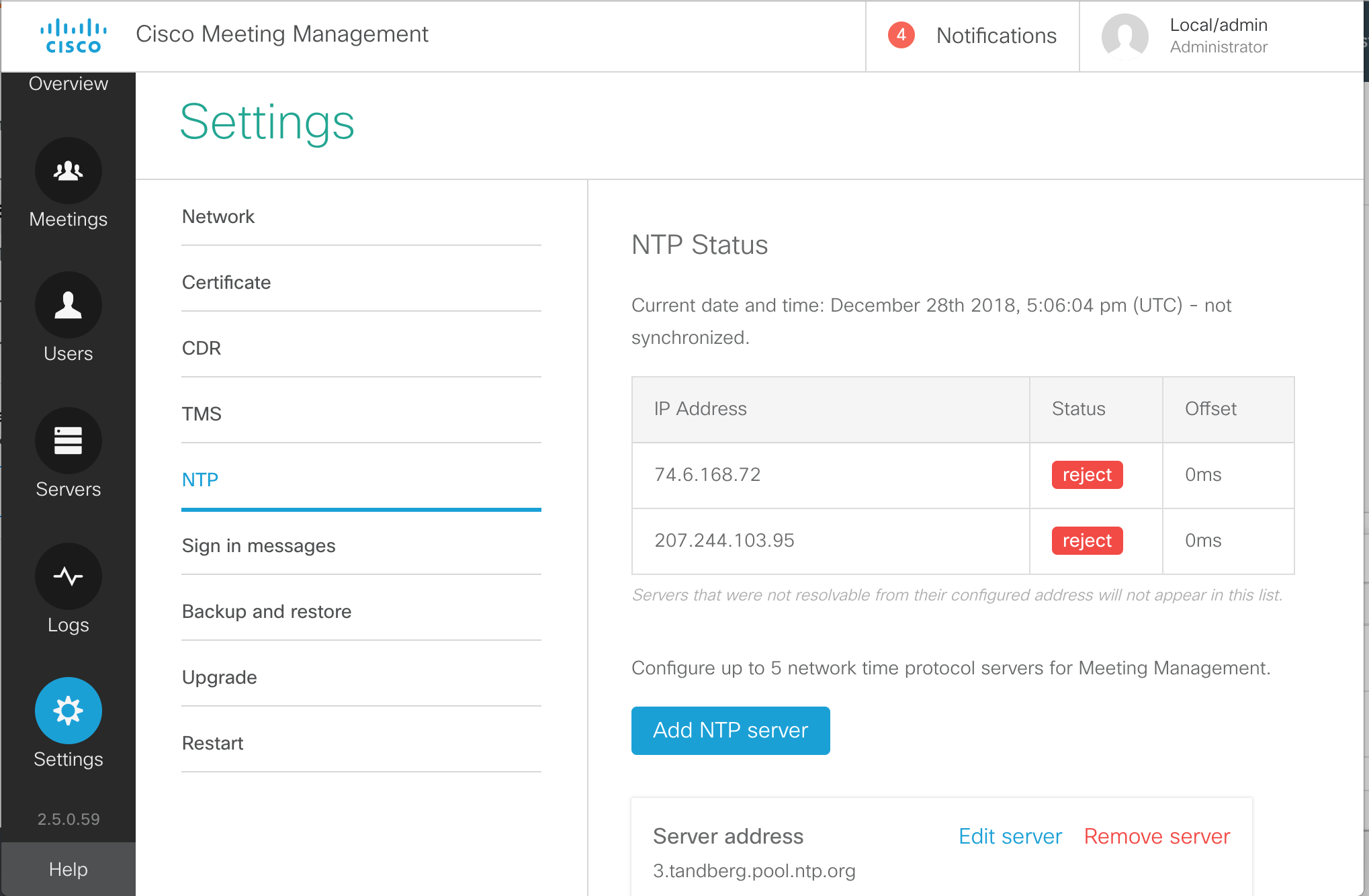
- You will see a few pre-configured NTP sources, which in most cases will not function. Let's first add our valid NTP source. Click Add NTP server.
- Enter 10.0.102.1
for the Server Address in the Add NTP server box.
- Click Add
- You'll notice that CMM reports a message at the top of the page indicating that a restart of Meeting Management is required. We'll ignore this for now, as each of these server-level tasks will require a restart.
- To clean things up, let's remove the pre-configured NTP sources. They will all be
tandberg.pool.ntp.org. One at a time, click Remove server next to each.
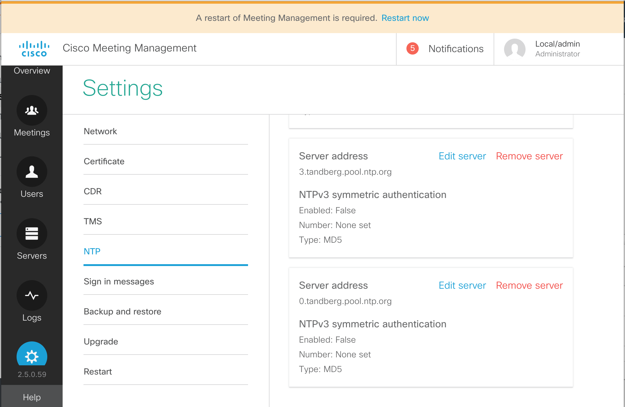
- Then confirm the tasks by clicking Remove in the confirmation box.
- Repeat this until only the single NTP server we configured, 10.0.102.1 is present.
- While still in the Settings section, click CDR
- Click on the CDR line.
- For the CDR receiver address enter the address portion of our CMM URL:
cmm1.pod2.cms.lab
- Press Save
- Click on Servers from the buttons on the left.
- Click Add Call Bridge now on the right.
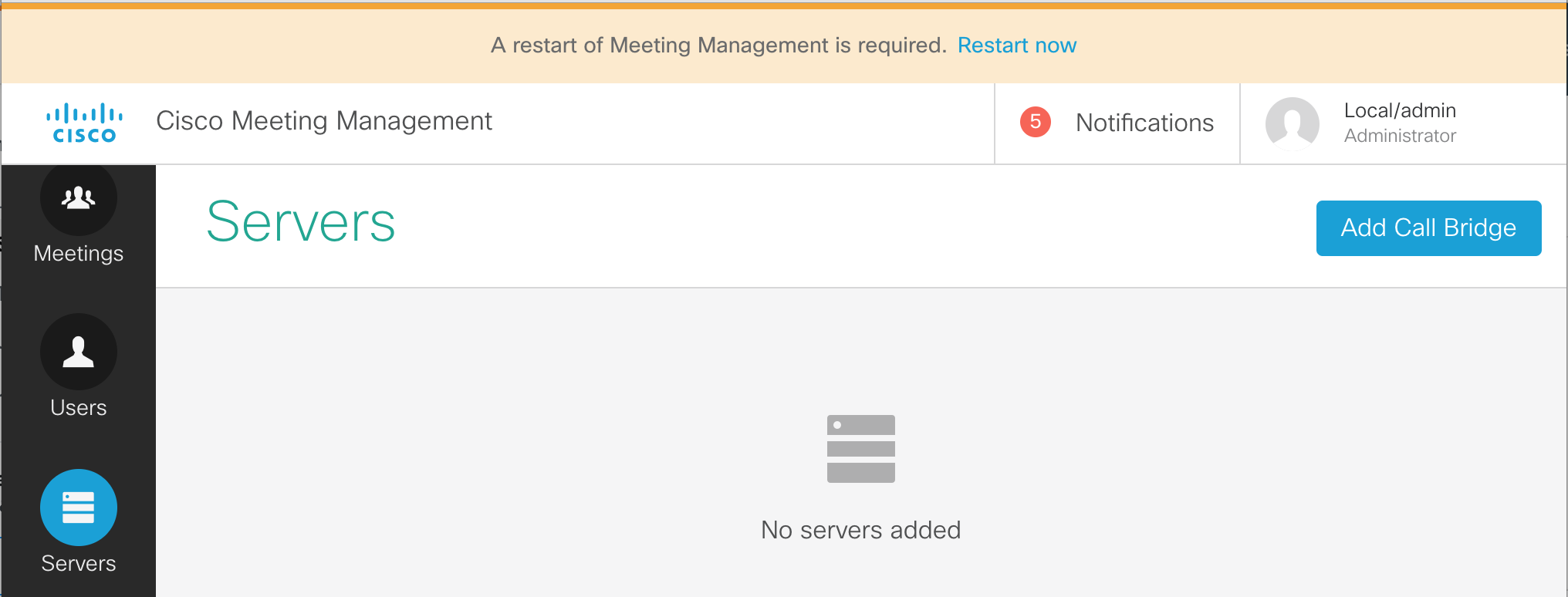
- Enter the information for cms1a. We do have DNS configured, so just enter cms1a.pod2.cms.lab in the Server address field.
- Enter the port for our web admin, 8443
- For the Display name field we can enter something that will make sense to the video conference operators. For example, let's enter POD2 CMS1a.
- Next we need to fill in the CMS API account credentials, apiadmin in the Username field and the Password, c1sco123 below it.
-
Finally, click the Add button.
-
You should now see a line with a Display name of Pod2 CMS1a.
The HTTPS column will show Unverified because
we are not using certificates that are trusted. We won't address that particular issue in this lab.
We do, however, need to add the other two Call Bridge servers that are part of our cluster
-
Below the added CMS server line you will see that it has 2 auto-discovered Call Bridges. Click the
show button to see cms1b.pod2.cms.lab and cms1c.pod2.cms.lab in the Server Address.
- Both CMS have the ? next to them instead of a check box next to the first column, meaning that they are not yet managed by CMM. To the right of cms1b.pod2.cms.lab server row (this may be the second or even the third row), in the Actions column, click the + button to add this Call Bridge.
- The Server address and Port are already pre-filled. To make things easier to identify, enter the Display name, POD2 CMS1b.
- The Username can be specified, apiadmin as well as the Password, c1sco123.
-
And press Add
- Once successfully, added, press the show button to see the last CMS, cms1c.pod2.cms.lab
- Press + at the right and we can enter the same information as before.
- For the Display Name, enter POD2 CMS1c.
- The enter the Username, apiadmin and Password, c1sco123
- Then the Add becomes active and you can click it.
- From the CMM administration screen, select the Users button.
- We see that there are options for LDAP user groups. Local users are configured in the Local section. Local credential policies are configured under Local configuration. We're interested in configuring our LDAP source. Click LDAP server
- On this page, there are a number of settings to configured. First of all, check the Use LDAP checkbox.
- For the Protocol, choose LDAPS, for secure LDAP.
-
The Server address should be set to
10.0.224.140. The port
should be 636.
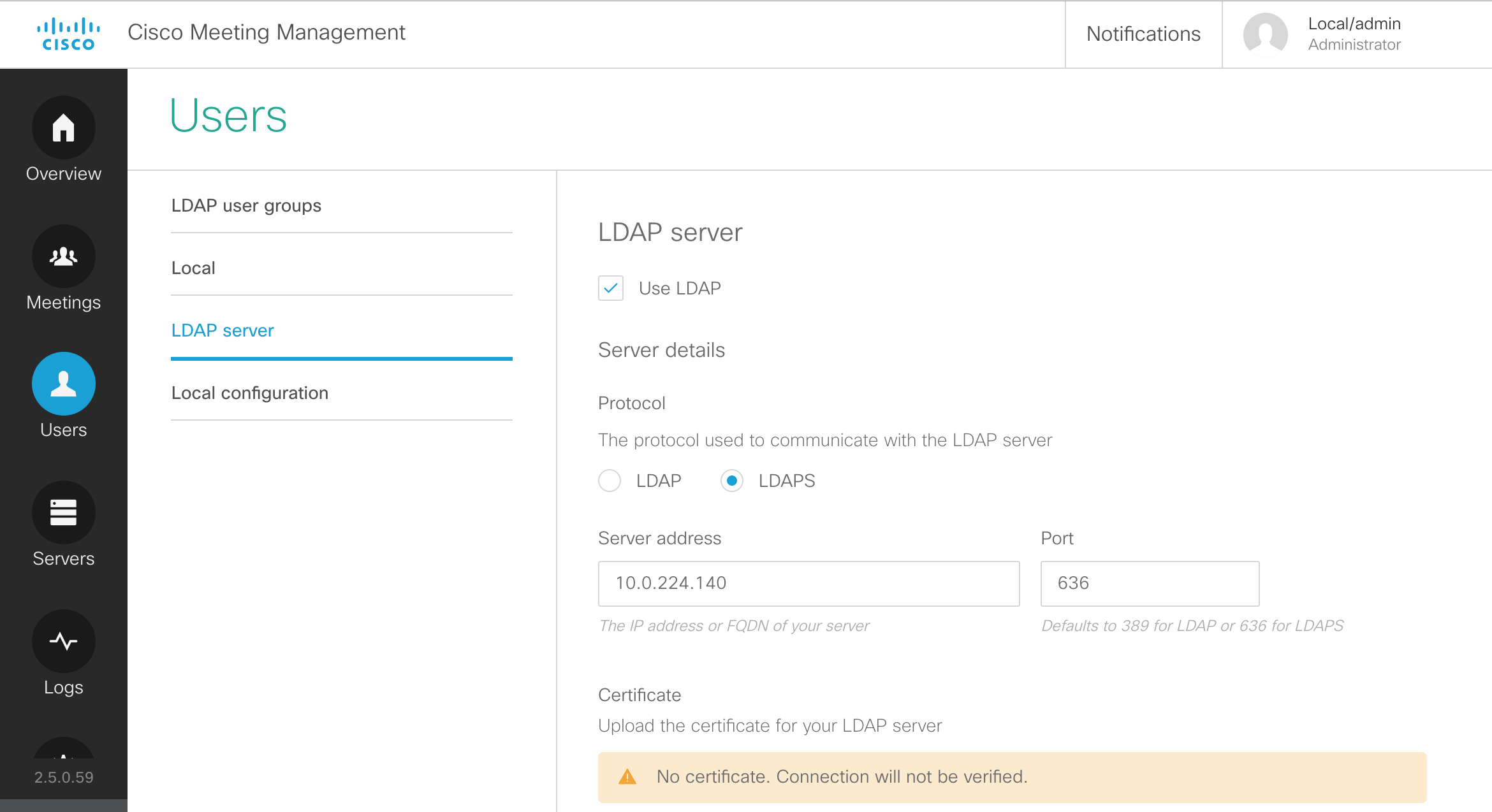
- We will keep the default certificate, but below in the Authorization section, configure CN=ldap,CN=Users,DC=cms,DC=lab
- Next, the Password for the Bind DN user account should be our usual c1sco123
-
The Base DN should be configured with:
CN=Users,DC=cms,DC=lab
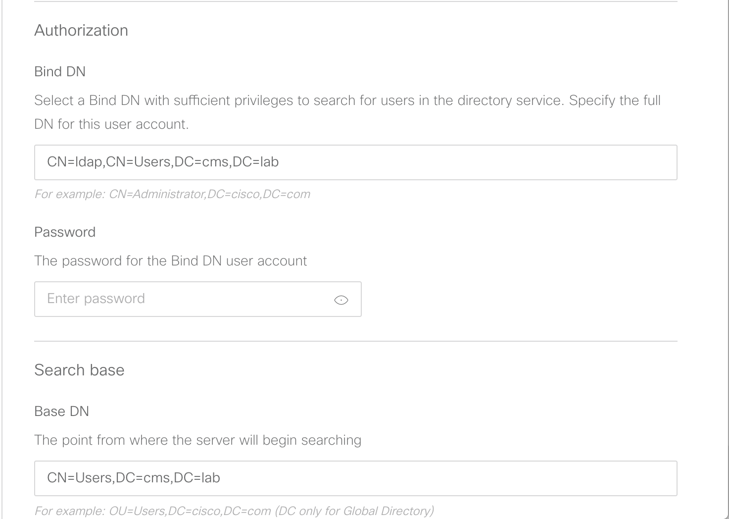
-
Leave the Search attribute set to sAMAccountName and click
Save
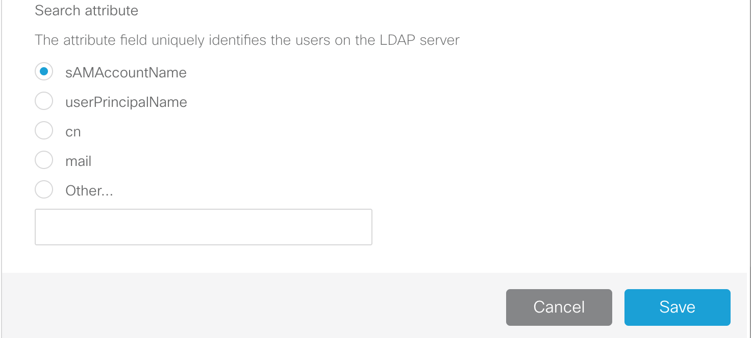
-
Navigate to the LDAP user groups section under the Users button.
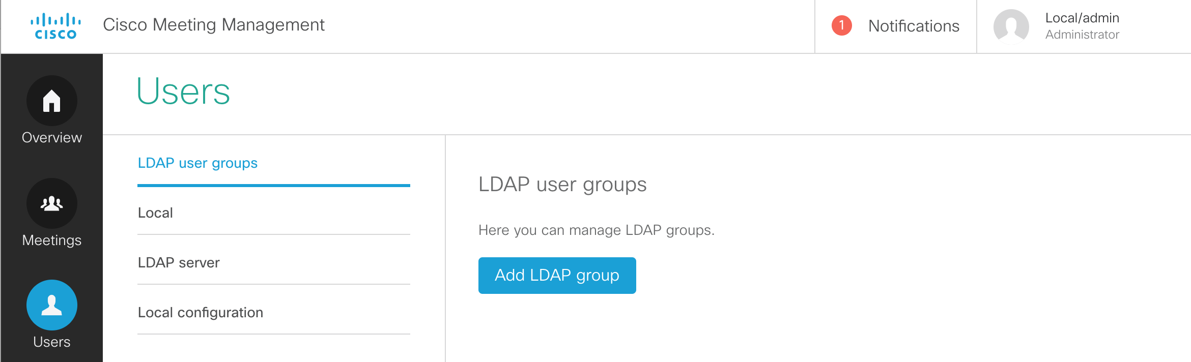
- You should now be able to click Add LDAP group.
- We need to configure an LDAP path. Enter CN=VideoAdmins,CN=Users,DC=cms,DC=lab.
- Click the Check button. This allows us to not only make sure the group can be retrieved, but also allows us to view the group membership.
- We see that there is 1 user associated with that group. Click View users and you'll see that the account is vidadmin. There is nothing to do and anyone who would be added to that LDAP group would automatically be granted access to the CMM.
- Check the Video operators button so that we can add this group of Video operators.
- Click Next
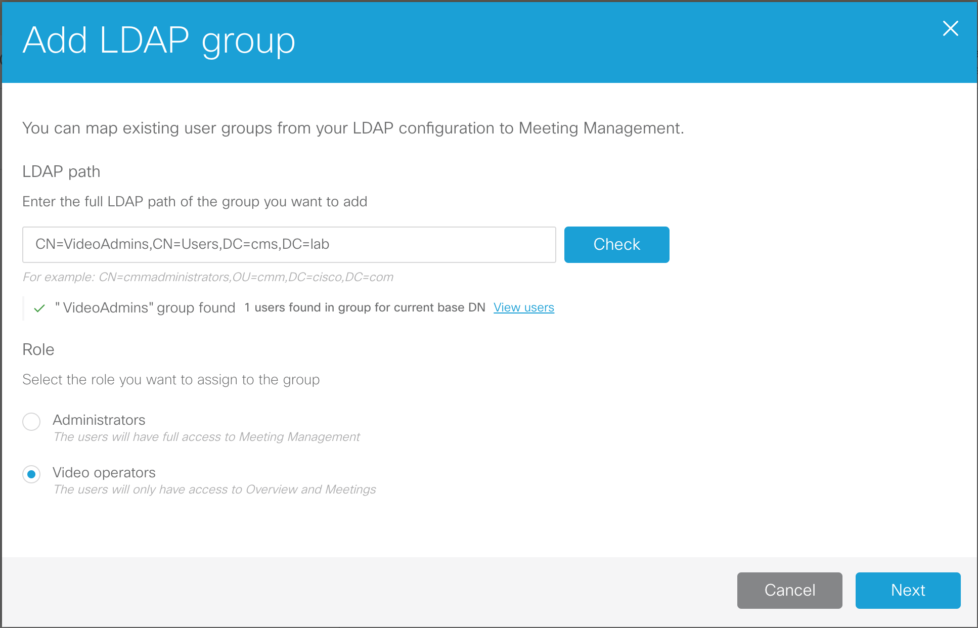
- The URL that would be given to the video operators can be configured here. In our case, this is simply the URL of the CMM itself. Click Done.
- This change also requires a restart. We have had restarts pending since earlier, but now it's time for us to complete the installation. At the top of the screen, in the red banner, click Restart now, followed by Restart.
- Browse to https://cmm1.pod2.cms.lab
- At the logon screen you'll notice that you now have a drop-down for LDAP and Local users. Select LDAP.
-
For the Username, enter our video admin user,
vidadmin
and password, c1sco123.
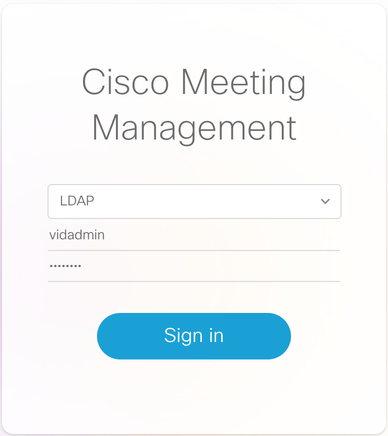
- Click Sign in
-
We see that we now only have the Overview and Meetings options and all the notifications have cleared.
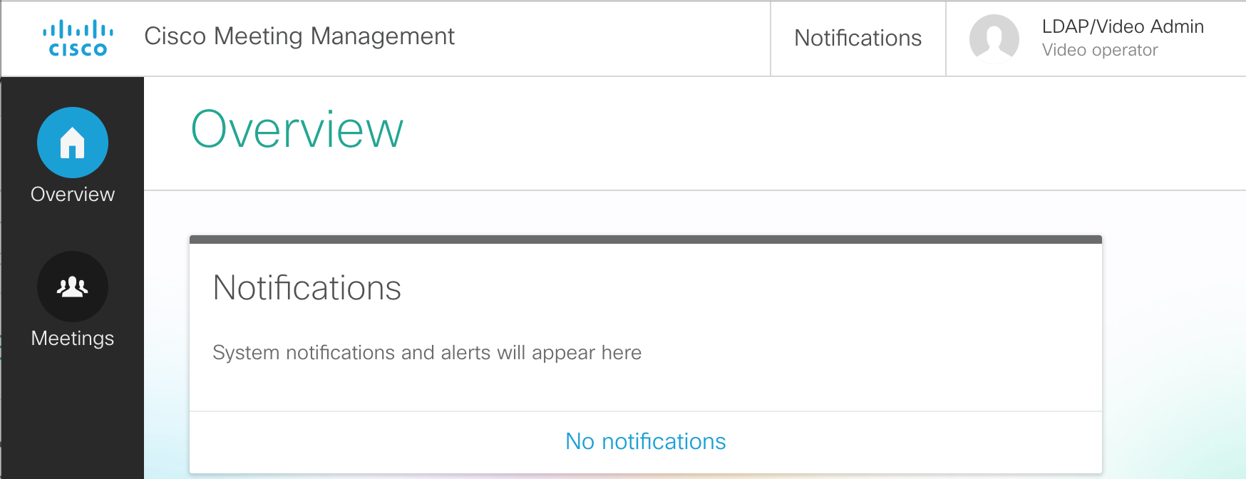
- In the CMM GUI, click on the Meetings button. You see that there are currently no active meetings.
- From your laptop's Jabber client, dial your personal Space at pod2user1.space@conf.pod2.cms.lab
-
The meeting should show up automatically if Active now is selected.
Click on the active meeting, Pod2 User1's Space, under the meeting title.
-
You see all participants, and have buttons to change the layout, record (if configured), stream the
meeting (if configured), and add participants. Let's add someone. Click the + button
under Add participants.
- For the participant's address to add, enter pod2user1@pod2.cms.lab and press Enter
- Then enter another participant, pod2user2@pod2.cms.lab and press Enter
- Click Add.
-
Both particpants are added. This may cause some feedback, but with CMM we can hover over each of the
participants and easily click the mute button.
-
If we click on our local user, the line with Pod2 User1, we can change that
participant's layout and see information about the call. You'll notice that we can see the display name
of the CMS that we configured previously, so you can tell which CMS this meeting is hosted on.
- When we're finished, click the End Meeting
-
Understand other CMS features, such as:
- Spaces, to understand more about how Spaces are organized and configured.
- Ad-hoc conferencing and integration with the Unified CM
- CallBridge Groups for load balancing calls
- Branding, for a more customized deployment.
-
Explore Cisco Single Edge with Cisco Expressway and CMS:
- Learn about deploying external WebRTC Web App using Cisco Expressway, to provide external users the same Web Bridge capability.
- Configure advanced Business-to-business calling with Skype for Business gateway calling.
- Investigate a Microsoft on-premise integration example, where you will learn about what is needed to configure a dual-home conferencing experience.
- Browse to https://cms1a.pod2.cms.lab:8443 (Note that we're browsing to CMS1C, there's a reason for this we'll see a bit later).
- You should see a login screen like this:
- Press Ok to get the username / password prompt.
- Then enter the credentials
(Username: admin,
Password: c1sco123)
and press Submit.
-
Once logged in, let's browse to the General page by using the menu shown below.
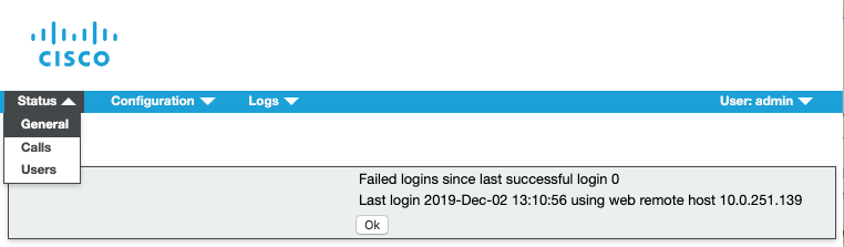
-
Take a glance at the page to see if there are any errors or warnings present. This page will list any Fault Conditions
and Recent errors and warnings. In the example below you can see a database connection error
in the Fault Conditions section and a schema version error in the Recent errors or warnings
section.
-
While still logged into CMS1C, let's browse to the Detailed Tracing page by using the menu shown below.
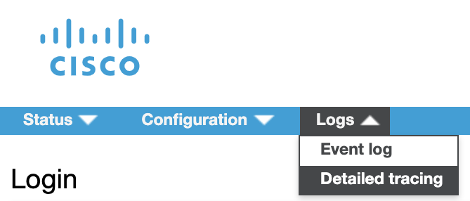
-
Currently, the detailed Sip Traffic Tracing is Disabled. Let's enable
detailed Sip Traffic Tracing for 24 hours by clicking the button shown below.
-
After doing so, instead of Disabled, it should now show as enabled for the next 23 hours, 59
minutes, and 59 seconds
-
Now, let's browse to the Event log page.
-
Clear the event log by selecting the Clear hyperlink as shown below and confirm by selecting
Ok
-
Now place a call to
pod2user4.space@conf.pod2.cms.lab
from the Jabber client.
-
After the call is established, click the download as text link which will take you to a text file containing the syslog
messages from cms1a which include detailed SIP messaging.
- Let's search for the SIP INVITE message for the call we just placed. Press CTRL + F on your laptop keyboard to bring up the Find dialog in your Chrome browser. Type INVITE sip:. Since we just cleared the logs, there should only be one SIP INVITE message in the log which comes into cms1a. In much the same way, you can search for other messages using this method to try to narrow down issues with SIP signaling, API-related problems, or any of the other items shown on the Detailed tracign page. This is a great first step in isolating problems.
-
You can now end the call by selecting the button from the Jabber
call window.
- Let's browse to https://cms1c.pod2.cms.lab:8443.
- If you've been logged out due to inactivity, you should once again see the login screen:
- Press Ok to get the username / password prompt.
- Enter the credentials
(Username: admin,
Password: c1sco123)
and press Submit.
- Once logged in, use your Chrome web browser's address bar to browse to https://cms1c.pod2.cms.lab:8443/debug.html (click to copy)
-
You'll be presented with the following page. Each of the hyperlinks on the page leads to another hidden page described above. Take some time to explore each of the pages to see the information contained therein.
CMS displays a landing page with some useful information regarding the current node including Version, Uptime, CPU Usage (current and average) and other information. In addition, there are links to other pages you can access from the Webadmin interface including cmd.html where you can issue certain CLI commands, memory.html where you can learn everything you ever wanted to know about memory allocation on the server, placement.html which has useful information about the current call processing node - in particular the free/used/limit information regarding the current node. What this means is that you can see a snapshot of your currently active node at any given time and how many calls it can handle. In addition to these there are several more pages worth looking at.
There are many items we could highlight to show the value of these hidden troubleshooting pages, but perhaps a useful example would be to take a look at would be on the placement page where we can determine what load the system is under and on different platforms like the CMS 2000 server can even show you what media module (blade) the call lands on.
-
Click on placement.html which will take you to the placement page, meant to show, among other things, how many media modules are in service and where the calls on CMS are being serviced from. On the CMS servers we're using, there is only one media module, but on the legacy Acano X-Series servers there were several, as well as on the CMS 2000 platform which is a current CMS platform.
As you can see, there's a lot of information on this page. In particular, notice that it shows the number of active calls present on this server. It also displays the resource utilization for the media module present within this VM. They are displayed in the format free/used/limit.
Notice, in particular, the line on the screenshot below which begins with
 .
If we were on the CMS 2000 platform, for instance, we would see 7 lines that begin this way, each of which
represent a separate media module (UCS Blade Server) on the chassis. Each media module is identified by a
name beginning with BEEF and subsequent modules would be denoted by 0200,
0300, and so on. There's a screenshot taken from a CMS 2000 below showing the additional
media modules as an example.
.
If we were on the CMS 2000 platform, for instance, we would see 7 lines that begin this way, each of which
represent a separate media module (UCS Blade Server) on the chassis. Each media module is identified by a
name beginning with BEEF and subsequent modules would be denoted by 0200,
0300, and so on. There's a screenshot taken from a CMS 2000 below showing the additional
media modules as an example.
- Now we're going to make a call with one leg hosted on CMS1C so that we can see the resource utilization on the placement page (this is the reason we logged into CMS1C instead of another node). Make sure you have a Remote Desktop session up on PC2 (10.0.102.92)
- Using Cisco Jabber on your laptop, click to call our Space at pod2user4@conf.pod2.cms.lab
- From PC2's Jabber client, call the same Space, but this time send the call to CMS1C by dialing pod2user4@cms1c.pod2.cms.lab
-
Refresh the placement.html page and you should now see that there are two active calls on CMS1C, one is the call we placed from PC2, and one is the distributed call joining the call on either CMS1A or CMS1B to this call because CMS1C is in a different Callbridge Group.
Note that we can see the resources consumed on CMS1C by looking at that middle number shown in the screenshot below. If this were a CMS 2000 platform, we could also tell what Media Module the call landed on, which might help to isolate issues observed to a particular blade server.
- When finished, use your laptop to disconnect PC2 User by hovering over User 2 in the participant list, then right-clicking the user and selecting Expel and confirming.
-
Once User 2 has been disconnected, hang up yourself by hovering over the video window and
clicking on the button.
-
Log into cms1a.pod2.cms.lab (password: )
-
Issue the following command from the CLI interface.
cms1a> -
You should start to see syslog messages scroll on your terminal window. As you might imagine, this method of troubleshooting
should be reserved for small issues or issues where a particular syslog message is expected when placing tests calls. If
we make our test call again to
pod2user4.space@conf.pod2.cms.lab,
we will see the same SIP INVITE message scroll by on the screen, but because of the volume of messages, it can get quickly lost.
-
Place a call to pod2user4.space@conf.pod2.cms.lab.
- From the CLI, use your keyboard to send CTRL + C to stop the syslog messages from scrolling by. You can scroll up and see the same SIP messages that we just observed via Web Admin, but because it's on the CLI it's not quite as easy to search and sort through. It is, however one more tool in your toolbox to try to isolate issues.
-
Log into cms1a.pod2.cms.lab (password: )
-
Issue the following command from the CLI interface.
cms1a> Packet capture running: press Ctrl-C to stop -
This will start the packet capture on cms1a.
-
Place a call to pod2user4.space@conf.pod2.cms.lab.
-
Let the call run for 30 seconds or so and then end the call with the button.
-
From the SSH session on cms1a press Ctrl+C.
cms1a> pcap a Packet capture running: press Ctrl-C to stop ^CTransferring packet capture: please wait... Packet capture available in admin-a-20191130-191054.pcap Captured 5201 packets, 424416 bytes cms1a> - As you can see, the packet capture was saved with a name denoting the interface, date, and capture number.
- Double-click the CMD icon on the Desktop. This will bring up a CMD window.
- Now let's establish an SFTP session to cms1a
to view the remote files
-
Now that you're connected to cms1a, let's download the packet capture to our local system.
First, let's get the name of the pcap by issuing the following command command:
psftp> dir admin* Listing directory / -r--r--r-- 1 admin admin 424416 Nov 30 16:37 admin-a-20191130-191054.pcap -
Next, get the packet capture by issuing the SFTP GET command for the filename in question. The filename will vary from pod to pod,
so make sure you copy the filename from your pod after you list the remote directory contents.
psftp> get ****YOUR PCAP FILENAME**** remote:/****YOUR PCAP FILENAME**** ==> local:****YOUR PCAP FILENAME****
- The file should now be on your local filesystem and able to be viewed by using Wireshark, but is outside the scope of this lab
- Double-click the CMD icon on the Desktop of your laptop. This will bring up a CMD window.
- Now let's establish an SFTP session from your laptop to cms1a
to view the files on the remote server.
-
Now that you're connected to cms1a, you should be able to list the files available by
issuing the command:
psftp> dir Listing directory / *** omitting certain files for brevity *** -r--r--r-- 1 admin admin 3642 Mar 01 16:37 ACANO-MIB.txt -r--r--r-- 1 admin admin 1267 Mar 01 17:06 ACANO-SYSLOG-MIB.txt -r--r--r-- 1 admin admin 286556160 Mar 23 23:19 upgrade.img -r--r--r-- 1 admin admin 96256 Mar 25 10:07 2_5_2.bak -r--r--r-- 1 admin admin 81666 Nov 04 10:12 cms1a.csr -r--r--r-- 1 admin admin 81666 Nov 04 10:12 cms1a.key -r--r--r-- 1 admin admin 81666 Nov 04 10:20 dbclusterserver.key -r--r--r-- 1 admin admin 81666 Nov 04 10:20 dbclusterserver.csr -r--r--r-- 1 admin admin 81666 Nov 04 10:20 dbclusterclient.csr -r--r--r-- 1 admin admin 81666 Nov 04 10:20 dbclusterclient.key -r--r--r-- 1 admin admin 81666 Nov 04 10:25 dbclusterserver.cer -r--r--r-- 1 admin admin 81666 Nov 04 10:25 cms1a.cer -r--r--r-- 1 admin admin 81666 Nov 04 10:25 cms1abc.cer -r--r--r-- 1 admin admin 81666 Nov 04 10:25 cmslab-root-ca.cer -r--r--r-- 1 admin admin 81666 Nov 04 10:25 dbclusterclient.cer -r--r--r-- 1 admin admin 2180404 Nov 04 14:22 call_branding.zip -r--r--r-- 1 admin admin 81730 Nov 27 08:47 boot.json -r--r--r-- 1 admin admin 81666 Nov 30 17:40 cms.lic -r--r--r-- 1 admin admin 81666 Nov 30 17:40 live.json -r--r--r-- 1 admin admin 1580636 Nov 30 17:40 audit -r--r--r-- 1 admin admin 84036440 Nov 30 17:40 log -r--r--r-- 1 admin admin 1 Nov 30 17:40 logbundle.tar.gz
Certain files have been highlighted because we have not talked about them previously in the lab. The upgrade.img file is the file used to upgrade CMS from a previous version. Any backups taken during the course of those upgrades will have the .bak extension, as you see 2_5_2.bak has. boot.json and live.json files, for instance, which are configuration files denoting the startup configuration and running configuration of the CMS server respectively. The audit log contains audit information regarding logins and errors for the CMS server. log is the syslog file which gets packaged in the next file we see, logbundle.tar.gz
Each of these files may be required for certain troubleshooting scenarios. In this case we want to make you aware of what they are and what information they contain
- Double-click the CMD icon on the Desktop of your laptop. This will bring up a CMD window.
- Change to the Downloads folder by entering cd %userprofile%\Downloads
- Establish an SFTP session to cms1a
to view the remote files
-
Now that you're connected to cms1a, issue the command:
psftp> get logbundle.tar.gz remote:/logbundle.tar.gz => local:logbundle.tar.gz - To gather diagnostic information on a call, there first must be a call to investigate. For this reason, we need to make a call that we know will land on one particular Callbridge. We will use a similar method that we used earlier in the troubleshooting section and insure our call has one leg hosted on CMS1C since it is the only node in the West Callbridge Group. Make sure you still have a Remote Desktop session up on PC2 (10.0.102.92), or re-establish one if you closed that window.
- Using Cisco Jabber on your laptop, click to call our Space at pod2user4@conf.pod2.cms.lab
- From PC2's Jabber client, call the same Space, but this time send the call to CMS1C by dialing pod2user4@cms1c.pod2.cms.lab
- Launch Postman using the desktop shortcut.
- Change the verb to GET.
- Enter the following URL in the address bar to target the calls entity. We need to get the call ID in order to enable
diagnostics for that call:
. Hit Send.
We should see the call information including the Call ID that we need to enable diagnostic information on this call.
-
The next step is to enable diagnostic information for this call. We need to copy the Call ID from our previous step
and use that in the the URL in Postman while changing our verb to POST Our final url will end up looking like this:
https://cms1c.pod2.cms.lab:8443/api/v1/calls/***CALLID***/diagnostics. Replace the Call ID with
your own. In this example the finished URL would be:
.
Make sure the verb is set to POST and hit Send
-
You should get a 200 OK message back. This message is important, because in the headers of that
message is a location we need to use for our next Postman transaction. If you look at the headers tab on the response we just received,
you'll see a location header.
-
Copy this location, and paste it in the Postman address bar followed by
/contents, so it looks something like this, then hit Send:
- What you should see is a good deal of useful diagnostic information about the current call. Take a look through the log information and familiarize yourself with the information returned.
- When finished, use your laptop to disconnect PC2 User by hovering over User 2 in the participant list, then right-clicking the user and selecting Expel and confirming.
-
Once User 2 has been disconnected, hang up yourself by hovering over the video window and
clicking on the button.
Configure the Call Bridges to connect to the XMPP Server
Start with cms1a by following these steps:
You should see that the XMPP connection is in a connected state.
Recorder Configuration
Now that we have our XMPP server configured, we will focus on the actual Recorder-specific configuration. For the purposes of our lab we will also assume that the NFS server exists on our network and has been preconfigured with a share to store our recordings. In our lab we are using a Widows server for this purpose, but any NFS share will work. Let's start by connecting to the command-line of cms1a via SSH:
Now, we want to configure the Recorder service on cms1a. Because we are configuring the Recorder on the same CMS node as the Call Bridge service, we need to change the default configuration slightly. We want the CMS server to listen on it's local loopback so that cms1a can send recordings to itself and then forward them to the NFS server. We also want to configure the Recorder to listen on the 'a' interface so that the other Call Bridges in the cluster are able to send recordings to it. We must also specify a port to run the service on. We will select a port which we know does not already have another service running. To accomplish this, we will issue the commands below:
Once we've told the recorder to listen on the loopback as well as the primary network interface, we need to set the certificate file to be used by the recorder. We can use the certificate we already have on cms1a as well as the private key file used by the Call Bridge, let's specify those now with the command below.
We also need to add the certificate used by the Call Bridge to the Recorder trust store. Since we have a cluster, we need to specify the trust bundle we created earlier so that the Recorder will trust any of the Call Bridge nodes that might send recordings to it. We will specify that bundle with our command below:
Now that we have the certificates specified, we need to tell the Call Bridge where we want to send our Recordings. As mentioned earlier, this needs to be specified as an NFS path that exists on our network. We are sending our recordings to a Windows 2008 R2 Server running NFS services, but any NFS service will work. We will specify the hostname of the NFS server, as well as the directory to store the recordings.
We also want to set the resolution of our recorded meetings to 720p which will allow us to save a bit of space while not compromising video quality. Set the resolution by issuing the command below:
Next, let's enable the recorder service. If everything worked correctly, you should see a success message.
Add the Recorder to the Call Bridge Using Postman
Now that we've enabled the recorder service on the command-line, we need to add the recorder to the Call Bridge using the API. To do that, we'll launch the Postman tool.
Next, we'll get the Recorder ID of the Recorder we just created.
Now we'll set the URL of the Recorder on the Call Bridge.
Now that we have specified the Recorder address, we should be able to record our meetings manually. Let's try a test call to make sure we see the 'Record' button and are able to initiate a recording. Then, we'll download the recording and play it back to insure it worked correctly. Jabber should already be launched and registered. First, place a call to pod2user4.space@conf.pod2.cms.lab directly from the Jabber client.
|
|
|
|
Now that we're in a conference call, we can invite others to be part of the recording.
The CMS Recorder will now encode and write the video recording to the NFS share which will be available in a few moments.
Your recording should now be available to view in your Downloads folder.
MAIN LAB COMPLETE!
You've finished the main portion of the lab. There are multiple additional optional lab sections, depending on your time and interest, to continue on.
Creating CMS Spaces
As mentioned earlier, any meeting hosted by Cisco Meeting Server takes place in what is known as a Space. Before Cisco acquired Acano, this was referred to as a coSpace and in the API the older coSpace terminology still persists, so any API method mentioning a coSpace is referring to what we today call a Space. Spaces can be created either via the WebAdmin GUI or API.
Spaces can be created through a variety of interfaces:
Technically, any integration to Unified CM for Ad-hoc conferencing leverages the API to dynamically create and remove Spaces on demand, as well.
While some configuration options can be made to an individual Space, all CMS settings related to call treatment and user experience in a Space are defined by a hierarchy of settings. Consider the following diagram. The values lower in the hierarchy will always override those in the higher, up to the global/system level. However if nothing is explicitly set in the lower profiles, then the higher level settings will be inherited.
For instance, the coSpaces object, which you can think of as a Space, can have settings defined via a callLegProfile (among other things) that are different from the global system profile. But within this coSpace, an individual coSpaceUser may have settings via a different callLegProfile that will override the coSpace's. This is how you can create, for example, a default layout with a different default for certain Spaces, with yet a different layout for certain individuals in the Space.
To create a simple Space, first take a quick look at the coSpaces server section of the API reference. The first thing to look at is to see if there are any mandatory parameters. These would have a * by the Parameter name. For creating the Space there are none, so we can simply peruse the guide for interesting settings:
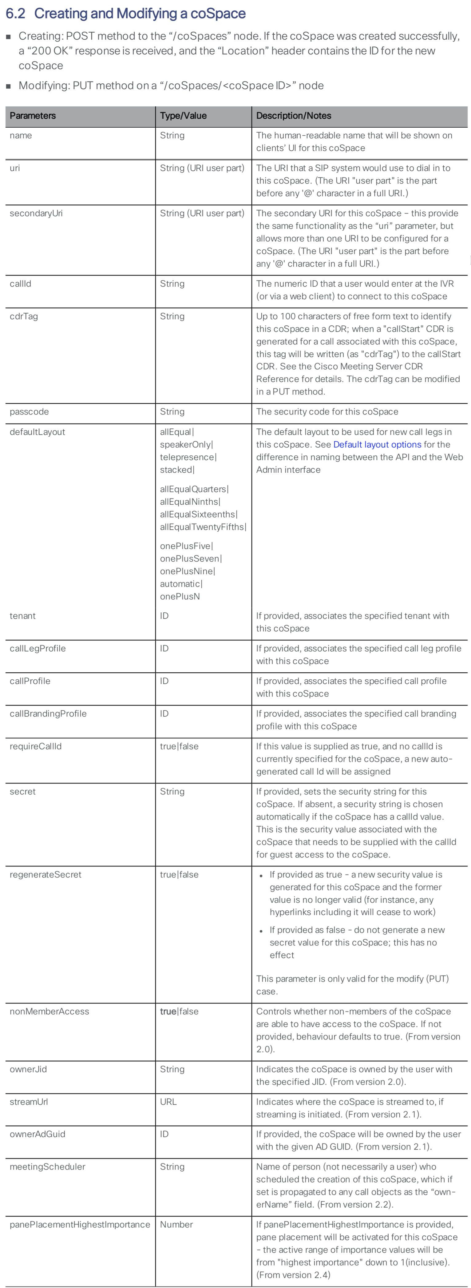
For purposes of the lab, you will create a simple Space using the API that we will then configure further.
|
|
|
|
Space Access for Host and Guest
Suppose you would like to configure this Space such that by default, people who call it will enter Guest access and are placed in a waiting room until a Host calls (using a different URI) and enters a passcode. To do this, you will create two callLegProfiles, one for the guest call behavior and another for the guest. Then the guest callLegProfile will be associated with the coSpace that you just created. The Host callLegProfile will then be attached to this same coSpace as an accessMethod.
SECTION COMPLETE!
You've finished this portion of the lab. We have multiple other optional lab sections, depending on your time and interest, to continue on.
Expressway-C Initial Configuration
While Expressway-E reboots, you can start configuring Expressway-C. This component sits on the internal enterprise network. It is the traversal client, establishing a tunnel from the inside to the Expressway-E in the edge network so that signaling can traverse the corporate firewall in both directions.
For this lab, your Expressway-C should already be configured with a system name, valid NTP server, and an internal DNS server. It also has its certificates and certificate authority certificates installed. Additionally, it has the Traversal Zones for Business to Business communication via the Expressway-E set up, as well as a zone to the Unified CM. The dial plan to use these zones is not yet set up and will be covered later as a part of this lab.
What remains to be configured is the following:
Enable Mobile and Remote Access (MRA)
As you did for Expressway-E, you need to enable MRA to enable the Web Proxy functionality. Again, you may see alerts that MRA is not configured properly or that a domain is not assigned. That is normal.
Configure Cisco Meeting Server
Now that MRA is enabled, you can also configure the Cisco Meeting Server on Expressway-C.
After saving the configuration, you should see that Expressway performed a DNS query and determined what servers this URI maps to. You should see the list of all of your CMS servers on the Expressway UI.
UC Traversal Client
The Expressway-C, as mentioned earlier, is the traversal client. This means that the initial traversal link setup always occurs from the C to the E. You configured the Expressway-E with a credential (the uctraversal user you created). Now you just need to create a traversal zone to tell the Expressway-C to connect to the Expressway-E. Follow these instructions to create the traversal zone:
You can refresh this information a few times, and eventually the zone should go Active.
Expressway-C Certificates
The reason the UC Traversal Zone went to a Active state is because the Expressway-E trusted the Expressway-C's certificate. Remember that the Expressway-E has the Certificate Authority that signed the Expressway-C's certificate in its Trusted Certificate Authority list. Secondly, the Expressway-C trusted the certificate that the Expressway-E presented.
Trusted Certificate Authority Certificates
Open the browser to the Expressway-C and navigate to Maintenance > Security > Trusted CA certificate. You should see the self-signed CA certificate ("Temporary CA"), the cms-CMSLAB-AD-CA, which signs the internal server certificates, such as the CMS servers and Unified CM, as well as the public-root-CA certificate which will allow us to trust the certificate that the Expressway-E presented to us.
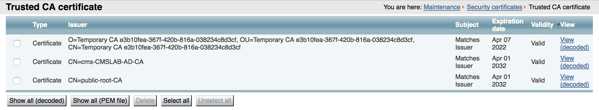
Expressway-C Server Certificate
The Expressway-E server certificate has already been installed. For the Web Proxy feature there are no special requirements for it. In this lab, it is signed by the internal, private Certificate Authority (cms-CMSLAB-AD-CA). This is important since you will have encrypted communication and calls everywhere.
Cisco Collaboration Edge with Expressway
The Cisco Expressway provides secure firewall traversal for voice and video and supports many features, such as Business to Business calling and Mobile and Remote Access (MRA) as well as TURN server capability. As such, it is what is referred to as the Single Edge solution and is Cisco's preferred edge solution for Unified Communications and the Cisco Meeting Server.
For this lab, your Expressway-E should already be configured with some of the basics, such as a system name, a valid NTP server, a public DNS server, and a valid, signed Certificate, so these operations will not be required, but they will be pointed out, when important. It also has a Traversal Zone and a DNS Zone, which is to say, an established communications trunk for SIP to the internal Expressway-C, and a dynamic trunk that can establish SIP communication to external video services or Business to Business SIP calls to and from external customers. The dial plan to use any of these zones is not yet set up and will be covered later as a part of this lab.
The Expressway-E has two interfaces in our deployment, one facing the inside of the network and one facing the external, public internet. The advantage of using a dual interface configuration is that you are then able to deploy an address on the external interface that is statically NAT'd to a real outside address, instead of requiring a public IP address (or requiring NAT reflection by the external firewall, which isn't often supported). However, without any NAT requirements, the Expressway-E could be deployed with a single interface. The single-interface deployment would be very similar to the dual-interface deployment you will do in this lab.
Web Proxy Overview
As you have seen, the Cisco Meeting Server can provide access to users using WebRTC-enabled browsers. For those same users to have access the Cisco Meeting Server when on the Internet, you can configure the Web Proxy feature in the Cisco Expressway. This requires a number of configuration steps.
Enable Mobile and Remote Access (MRA)
The first step in setting up the edge is to enable MRA. If you are familiar with the MRA feature you may find this requirement to be non-intuitive. MRA relies on the web proxy feature of Expressway, so to enable the web proxy feature, you must enable MRA, even if you are not actually deploying the MRA solution. You may see alerts indicating that MRA is not configured properly or that a domain is not assigned. This is normal if you are deploying web proxy for CMS, but not deploying the full MRA solution. Follow these steps to enable MRA on your Expressway-E:
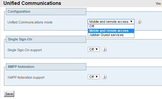
Change Expressway-E Web Administration port
When you are finished deploying the Web Proxy, you want end users to be able to enter a URL in their browser and reach the CMS Web Bridge. If left unchanged, the default port number for the Expressway Web Admin is port 443, which means that instead of connecting to the Web Proxy and reaching CMS, users would connect to the Expressway Web Admin. You can change the port that the Web Admin uses so that the default HTTPS port, 443, can be used for Web Proxy. Follow these steps to change the port number for Web Admin:
UC Traversal Server
The Expressway-E server typically sits in the DMZ and has an interface that is directly reachable from the Internet (and in some cases this address is a NAT'd address). Most firewall policies do not allow connections from the DMZ to the internal network. However, most firewall policies do allow connections from the inside to go out to the DMZ and Internet. The Expressway-E is configured as a traversal server where it can accept connections initiated from traversal clients, such as Expressway-C, that are on the inside network. This connection is then used for bi-directional communication, allowing messages from Expressway-E to be sent to the Expressway-C that established the traversal connection. For Web Proxy, this traffic is HTTPS traffic to and from a web client on the Internet, which requires a type of traversal zone known as a UC traversal Zone. This is different than the typical Traversal Zone used for Business to Business communications, so unless the MRA feature was previously deployed on your Expressway, this would be a new requirement.
For the traversal connection to work, the Expressway-E must have a user that the Expressway-C will later use to authenticate. Follow these steps to add this user:
Now configure the UC Traversal zone:
Certificates
Certificates on the Expressway-E are extremely important, since clients, whether a web browser from an Internet user or another company trying to communicate with your enterprise, must be able to trust the authenticity of the server they're connecting to. Therefore, Expressway-E certificates, in particular, should be signed by a trusted public Certificate Authority (CA) (e.g. Verisign, GoDaddy, etc...). The Expressway-E also needs to trust the connections from its internal clients, which are the Expressway-C traversal client and CMS as a TURN client. Because of these two requirements, the Expressway-E should have the root certificate from both the internal CA that signed the internal device certificates, as well as the CA that signed its own server certificate, loaded into the Trusted CA certificate store. These steps have already been done for you to save some time, but follow these steps to look at what has been done:
Trusted Certificate Authority Certificates
Open the browser to the Expressway-E and navigate to Maintenance > Security > Trusted CA certificate. You should see the self-signed CA certificate ("Temporary CA"), as well as the public-root-CA certificate, which will sign the certificate request from this server, and the cms-CMSLAB-AD-CA, which signs the internal server certificates, such as those from the Expressway-C and the CMS servers.
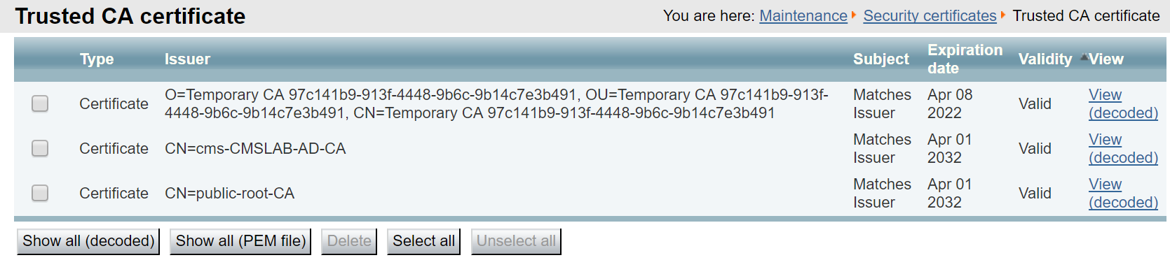
Although the Expressway-E has the root CA certificates, we need to check if it has a CA-signed server certificate. If it does not, you would first create a Certificate Signing Request, download the CSR, submit the CSR to the CA, and install the new certificate. But first, let's check.
Expressway-E Server Certificate
The Expressway-E server certificate has already been installed as well. To examine, open the browser to the Expressway-E.
The system will now restart, which typically takes 2-3 minutes. The Expressway-E configuration is now complete. Don't forget that when it comes back, the administration GUI for Expressway will now be on port 445! While booting, you can continue with the next section by configuring the Expressway-C.
TURN Service
TURN stands for Traversal Using Relays around NAT. Basically it is a device that sits on the public Internet that sends and receives media. To function correctly, it must be reachable by both the external devices on the Internet and internal devices, such as CMS, so that audio and video traffic can flow into and out of an organization. The TURN server in this case acts as an anchor point for the media that is trusted by the firewall.
The CMS server can be deployed as an edge device and function as a TURN server, but since the Expressway-E has TURN server capabilities as well, that is what you will use for this lab. Regardless of which device is used as a TURN server to anchor media, the TURN server must be configured in the CMS database so that the Call Bridges know where to send media and, since the TURN server is on the public internet, the web client can know where to send its traffic. An Expressway-E, acting as a TURN server, will bridge the traffic received on its internal and external interfaces together so that users can establish two-way communication.
For any device to use a TURN server, authentication is required. You should configure another set of
authentication credentials on the
Now you can configure the Expressway-E TURN server.
While the Expressway-E is restarting, you can focus on CMS again. Now that the TURN server is enabled, Cisco Meeting Server needs to be made aware of it. The only way to configure it is via the API. Start by looking at the API reference to see how to set up and modify a TURN server.
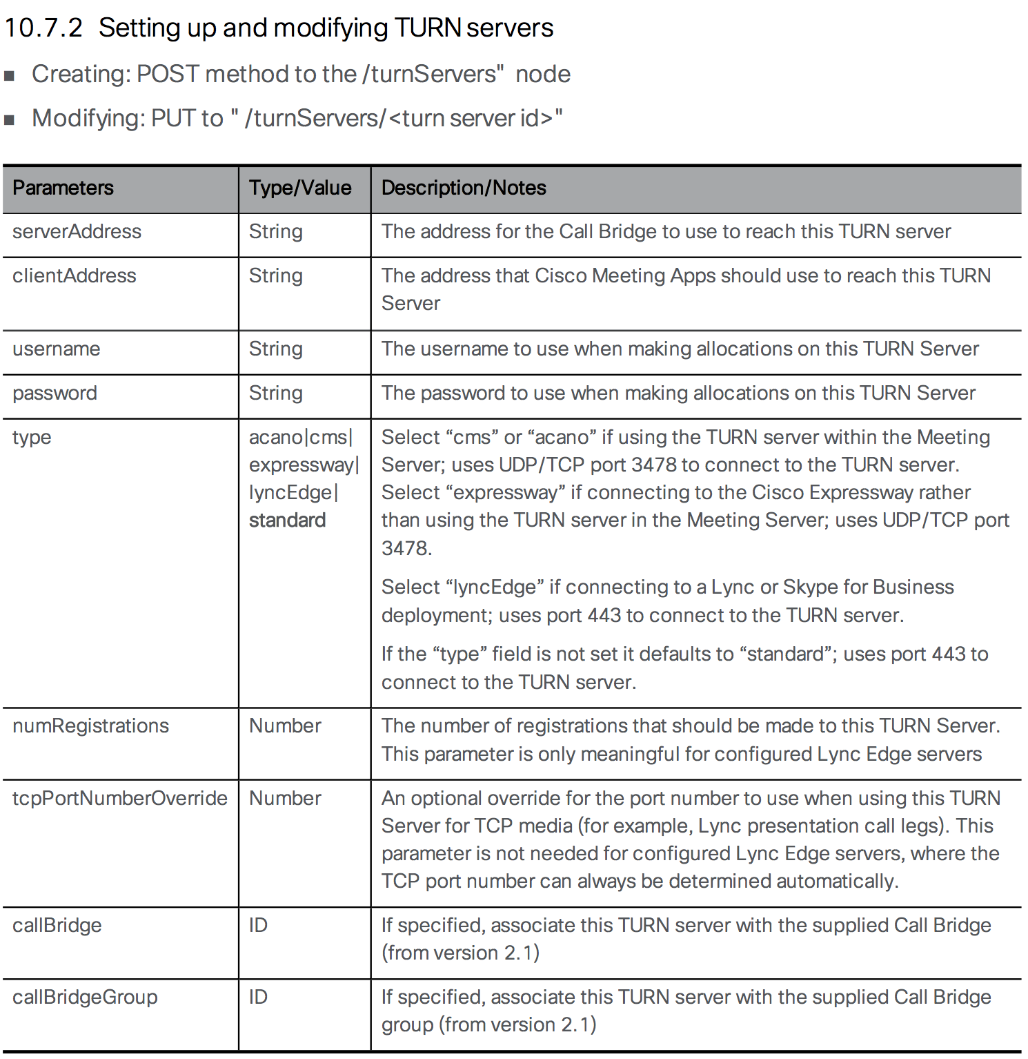
Follow these steps to configure the TURN server on CMS:
Assuming you received a 200 OK response, use the GET method to examine the configuration.
By default, every CMS server maintains its own connection to each TURN server.
Test Web Proxy Access and TURN
Now that TURN is configured and operational, you should be able to join a Space from a WebRTC client on the outside of the network. PC3 has been set up for this purpose. It is on the "outside" in that it has been completely firewalled so that it cannot reach any of the internal devices, except for the Expressway-E's external IP addresses, which is used for Web Proxy, TURN, and SIP signalling. The only way for this PC to reach the CMS server is to go through the Expressway-E and Expressway-C.
To test your TURN configuration, you need to access PC3 via Remote Desktop. Follow these steps to perform the test:
You now have WebRTC and TURN configured. If you like, you can now continue on to add support for Skype for Business/O365 gateway calling. This is especially useful if you don't have an on-premise Lync/Skype for Business deployment. Alternatively, you could take a look at the Microsoft on-premise integration example, where you will configure a dual-home conference with an on-premise Skype for Business deployment. Alternatively, you could take a look at Cisco Meeting Management for white-glove services and easier visibility of meetings in a clustered environment.
SECTION COMPLETE!
You've finished this portion of the lab. We have multiple other optional lab sections, depending on your time and interest, to continue on.
Configure Zones for B2B on Expressway-C
Now that you have configured the dial plan for inbound and outbound calls on the Expressway-E, you can turn your attention to the Expressway-C. Recall that you already have the Zone to UCM configured as well as three Zones for CMS, one for each individual server. You only need a rule to route calls that don't match the local Unified CM or CMS domains to the traversal zone so that it will reach the Expressway-E.
Finally, we need to verify that TURN is configured and place a test call.
Business to Business Calling through Expressway
Business to Business (B2B) video communication is a core feature of the Expressway product. You will configure it in this lab as a stepping stone to enabling external B2B calls to Microsoft Skype for Business, which is basically a more complex version of a B2B call. B2B allows users to place video calls inbound and outbound from the enterprise to and from external video services or customers over the Internet, while traversing the corporate firewalls in a secure fashion.
At the heart of B2B calling is the Expressway's call routing capability. While it can perform domain-based routing like Unified CM and most other SIP call control entities, it also has the notion of a DNS zone. This is basically a wildcard destination and is configured on the Expressway-E, the component closest to the edge of the network. You do not need to explicitly define a remote destination. Instead, Expressway uses DNS to find the destination. This DNS Zone is already set up for you.
The DNS zone first performs a variety of DNS SRV lookups attempting to find the destination for the domain that is being called. For SIP, it looks for _sips._tcp.domain and/or _sip.tcp.domain depending on the security and encryption settings. If any of those SRV lookups fail, Expressway can be configured to also perform standard A record queries to find the destination. For the purposes of this lab, you will only be using SIP over TCP and leveraging SRV records in DNS to facilitate the connectivity. These lookups allow the Expressway to route calls to destinations that are not explicitly defined. The customer or video service can simply register these DNS SRV records in a public DNS and then automatically be able receive calls from external customers or clients. This is often referred to as an open federation.
A Traversal Zone which accepts a connection from the Expressway-C has already been set up for you, as well.
Configure Dial Plan on Expressway-E
Now you can focus on configuring the dial plan on the Expressway-E. The dial plan will consist of only two rules. One rule will match anything destined to the local domain (pod2.cms.lab) or the CMS domain (conf.pod2.cms.lab) and send those calls to the Traversal Zone, as these calls are destined to the enterprise. The other rule will match anything else that did not match those two domains and route them to the DNS zone to find the destination on the Internet.
Next, add a rule for the DNS zone. Instead of matching a wildcard, you will define the rule that matches any domain that does NOT match the local domains. Additionally we specify that the source of the call must be the Traversal Zone. We don't want external calls to be hairpinned back out via this zone.
Now we can move on to the Expressway-C configuration.
External Microsoft Federation Overview
Now you're ready to add B2B capabilities with federation to external Microsoft Office 365/Skype for Business users. For the rendezvous-type calls, all the work is already done. The Expressway-C is already routing calls for the CMS domain (conf.pod2.cms.lab) to the CMS servers (cms1a, cms1b, cms1c) and these servers are perfectly capable of handling Microsoft SIP-based calls.
The other call flow is a gateway call, where you allow direct point-to-point calls between standards-based SIP endpoints and external Skype clients, utilizing CMS as a transcoder, without the end-user having to do anything other than dial the destination's URI. Inbound calls are fairly straightforward. A call to the UC domain that is of the Microsoft variant should first go through CMS before being sent to the Unified CM. Outbound calling is more complex. While it is easy to configure when the external domains involved are known, for this lab we will configure an open federation, where any external domain can be called without knowing in advance if it supports standards-based video or is a Microsoft SIP-based destination. Essentially, we will try standards-based SIP and if that fails, we will route the call through CMS and re-attempt as Microsoft SIP.
Beginning with the X8.9.1 release, Cisco Expressway has a feature where it can distinguish between standards-based SIP calls and various Microsoft SIP variants based on the headers present. If, for example, an inbound call arrives from a Skype for Business user destined for a standards-based Unified CM endpoint, the Expressway-C can send the call to CMS. The CMS can perform the interworking and send the call back to Expressway-C as a standards-based SIP call, which can be routed to the Unified CM.
Consider the two call scenarios:
Expressway-C Search Rules
Remember the goal of this interoperability with Skype for Business is to send Skype calls through the CMS server so they can be converted to Standards-based SIP. Consider each call flow, starting with a call from an external Skype for Business user dialing a user in the Enterprise (e.g. a Jabber user).
Inbound Skype for Business Calls
Any external Skype for Business / O365 site will use DNS to locate the Expressway-E, which will send the call to the Expressway-C.
For an external Microsoft Edge server to locate your network, the public DNS server requires the SRV record _sipfederationtls._tcp.pod2.cms.lab configured to resolve to the Expressway-E's external facing IP address. This SRV record is already set up in our lab's public DNS server. When a Skype for Business user places a call, the Microsoft Edge server looks for this DNS record for the domain being called and routes the call to the address it finds, thinking that it is communicating with another Microsoft Edge server. The Skype for Business call arrives at the Expressway-E which sends the call via the Traversal zone to the Expressway-C because the destination domain is our UC domain, pod2.cms.lab. Once the call arrives on the Expressway-C, that server needs to identify that the call contains the Microsoft SIP call variant and route the call to CMS. The CMS, in turn, receives the call and, recognizing that the destination domain is pod2.cms.lab, forwards it and, using an outbound rule, sends the call back to the Expressway-C as a standards-based SIP call. The CMS then anchors the call, performing the Microsoft-to-standards-based SIP interop. The Expressway-C, using Search rules already configured, can send the now-standard SIP call to Unified CM.
First add a rule to Expressway-C that will accept calls that have the Microsoft SIP variants and route them to CMS. As before, since we have a cluster, we must route the calls sequentially through each CMS node, each rule having a higher priority, and then stopping after the final CMS node is attempted.
Click HERE to configure the Search rule for CMS1b and CMS1c or configure it manually by expanding the detailed steps. This rule will be identical to the one just configured, except for the name, priority, and in the case of the last rule, the match behavior will be to Stop
As before, we must consider the failover scenarios and add the same rules for CMS1b and CMS1c. First for CMS1b:
And finally a search rule for CMS1c. This one will no be set to Stop routing if it cannot accept the call.
Now inbound Skype for Business calls to the UC domain are sent to the CMS where it will accept the call and then forward it back to the Expressway-C as a standards-based SIP call because of the outbound rule configured for pod2.cms.lab as Standards-based SIP. Expressway-C already has a rule that matches standards-based SIP calls destined to this local UC domain, and routes them to the Unified CM (the UC domain StdSIP to CUCM rule). Inbound calls should work now. But what about outbound calls?
Outbound Skype for Business Calls
We already have a generic outbound B2B Search Rule in the Expressway-C. As we have seen, we can make successful outbound B2B calls. If you recall, this Rule ("Outbound Zone"), had a pattern behavior of Continue. This is because we need the subsequent Rules for when those calls fail because the domains are not registered as standards-based SIP domain in the public DNS. Instead, we will need to route those calls to CMS, which will then send them back as Lync-type calls, which will then be handled by the Expressway-E and routed to a Microsoft domain.
Consider a call from an internal endpoint destined to the URI bgates@microsoft.com. Unified CM and Expressway have no idea if this is a call destined to a Skype for Business user or a Standards-based SIP endpoint. Expressway will initially think this call is to a Standards-based SIP endpoint. Looking at the rules you have configured so far on the Expressway-C, the Outbound Zone rule will be matched to send the call to the Traversal Zone. You should note that this rule has the On successful match parameter set to Continue. You will see why that is important in a moment.
The call is extended to the Expressway-E. Expressway-E then matches its rule that routes the call to the DNS Zone, as it is to a non-local domain. Since this call still contains none of the Microsoft-specific headers, this is assumed to be a standards-based SIP call. Therefore, Expressway-E when routing to the DNS Zone, the Expressway will ONLY send a standards-based SIP SRV request to the public DNS server, in the case of this example, _sip._tcp.microsoft.com or _sips._tcp.microsoft.com. If the destination is a Skype for Business / Office365 site, they should not be advertising those DNS SRV records (otherwise they have the responsibility to actually support standards-based SIP calls). This means these SRV lookups will fail. As a result, Expressway-E rejects the call that came from Expressway-C with a 404 Not Found message.
Remember that the Outbound Zone search rule initially matched on the Expressway-C was set to Continue? This parameter tells Expressway-C to continue searching through the rules if there was no successful call completion. So what we can do at this point is insert a new rule to send calls for a non-local domain to the CMS. The CMS should route the call back to the Expressway-C, but this time with the Microsoft variants included. This new call matches another new rule, which will state that calls from the CMS with Microsoft SIP variants should route through the traversal zone to the Expressway-E. There it matches the same rule for the outbound DNS Zone, however, now the call actually has a Microsoft variant, which means that the Expressway-E will automatically issue DNS requests for _sipfederationtls._tcp.microsoft.com. This will resolve to the IP address of an external Microsoft Edge server and the call can proceed, all the while being anchored at the CMS for interoperability between the SIP variants.
To summarize, the way outbound calls work is Expressway first attempts to route the call directly using the Standard SIP variant and if that fails, it tries sending the call through CMS so that it can attempt the call as a Microsoft-variant call.
You just need to add a few more rules to the Expressway-C to implement the above requirements. The first is to match calls to non-local domains and send them to the CMS, but at a lower priority (higher priority value) than the existing Outbound Zone rule (with priority 150) so that it only applies if the standards-based call fails.
Now we add the same rule for CMS1b.
Click HERE to configure the Search rule for CMS1b and CMS1c or configure it manually by expanding the detailed steps. This rule will be identical to the one just configured, except for the name, priority, and in the case of the last rule, the match behavior will be to Stop
Now we add the same rule for CMS1b:
And finally we add the rule for CMS1c:
Expressway Loop Prevention
One of the challenges with this dial plan, is that it can be prone to routing loops if care is not taken. Specifically, CMS will be configured to forward all domains and then have multiple default routes, because a call may be destined to an unknown domain that is either standards-based or Microsoft SIP. The way we prevent loops here is by adding rules for calls originating from any of the CMS zones destined to unknown domains to route to the Traversal Zone (the Expressway-E) but then stopping.
Part of the complexities of this lab is that between an open federation model and support for numeric dialing from CMS, requires the CMS to have have a rule that forwards calls for all domains and then multiple default routes, since the outbound calls could be destined to Microsoft or standards-based SIP destinations. Basically, anything sent to CMS that is not destined to CMS will be returned as one form of SIP or another. Since Expressway has Search Rules that attempt an external call, then one of the CMS (then another, then the other), there is a huge risk for routing loops.
To mitigate this, we will add a Search rule that takes priority over the other outbound Search rules, such that calls originating from the CMS zones can try the Outbound Zone but will then Stop (as opposed to being sent back to potentially a different CMS).
Now we add the same rules for traffic originating from CMS1b and CMS1c.
Click HERE to configure the Search rule for CMS1b and CMS1c or configure it manually by expanding the detailed steps. This rule will be identical to the one just configured, except for the name and source Zone
Now we add the same rule for CMS1b:
And finally we add the rule for CMS1c:
CMS Call Routing
CMS Incoming Calls
From the CMS point of view, any call it receives that is destined to the UC local domain should be forwarded, then sent outbound using standards-based SIP trunk type. Any calls that arrive destined to a non-local/unknown domain should be forwarded and sent as a Lync trunk type. Also, any call that arrives using any of the CMS' FQDN's should be forwarded as well. This is important because Skype for Business users will perform callbacks to the CMS' FQDN domain, a limitation of us anchoring the call at CMS.
The Incoming call portion can be configured from the Web Admin GUI of CMS. Recall that CMS first consults the Call matching rules to see if the domain is to be treated as something that has a CMS-based Space, user, or IVR. If that doesn't match, it looks at the Call forwarding rules to see which domains should be forwarded, which means then that they would be subject to the Outbound calls rules. We want that to happen for every domain.
That's it. Everything that doesn't match the CMS domain gets forwarded. Now you must configure the Outbound calls rules.
CMS Outbound Calls
For Lync-type calls in a clustered CMS environment, there is another consideration. For outbound calls from CMS, the Local contact domain must be set to the FQDN of the CMS server from which it originated. By default, the Local contact domain will also be used in the From field as long as "use dial plan" is configured in the forwarding rules for that domain. The From value, in turn, will be used by the S4B destination for callbacks and content sharing. How do we ensure that the outbound rule will fill in all this based on the specific CMS server that it is using? This is done via Call Bridge Scoping.
An example will make this clearer. Because we require Call Bridge scopes, we will need to configure the outbound rules via the API.
If we navigate to CMS1a Outbound Rules (admin / c1sco123), we note the following added rules:
You'll notice the Call Bridge Scope at right has been set and should match the CMS server's fully qualified domain name in the Local contact domain column. Since we were querying CMS1a, the Call Bridge Scope for CB_cms1a shows "<local>"
Test Skype for Business Calls
Now that you have B2B configured and CMS is ready, you should try three different call types:
First try calling into a Space. You will need to initiate a call from each of the clients.
You should now be in the same Space with the Lync user. Feel free to call that same URI from the other Jabber users on PC1 and PC2. You can also try application sharing. This sets up an additional call for the Skype for Business user. You can monitor this on the CMS. Once finished, disconnect all call legs.
Now try calling from Jabber to the Skype for Business user at skype2@ms.lab. Be sure to access PC3 and answer this call with video, as there is no auto-answer.
|
|
|
Skype for Business User Answers |
|
You should now have an established call between Jabber and Skype for Business.
|
|
|
Next, reverse the call flow and call from Skype for Business to Jabber. The Skype client must call pod2user4@pod2.cms.lab, the URI of User4 on your laptop. You should find this in the Favorites folder of the Skype for Business client.
You should now have the same call up as before, but initiated from Skype for Business. When done, disconnect the call from all endpoints.
SECTION COMPLETE!
You've finished this portion of the lab. We have multiple other optional lab sections, depending on your time and interest, to continue on.
TURN Service
If you already completed the External WebRTC section, then you already have TURN configured. If not, you can expand the Configure TURN section below and configure it.
TURN stands for Traversal Using Relays around NAT. Basically it is a device that sits on the public Internet that sends and receives media. To function correctly, it must be reachable by both the external devices on the Internet and internal devices, such as CMS, so that audio and video traffic can flow into and out of an organization. The TURN server in this case acts as an anchor point for the media that is trusted by the firewall.
The CMS server can be deployed as an edge device and function as a TURN server, but since the Expressway-E has TURN server capabilities as well. That is what you will use for this lab. Regardless of which device is used as a TURN server to anchor media, the TURN server must be configured in the CMS database so that the Call Bridges know where to send media and, since the TURN server is on the public internet, the web client can know where to send its traffic. An Expressway-E, acting as a TURN server, will bridge the traffic received on its internal and external interfaces together so that users can establish two-way communication.
For any device to use a TURN server, authentication is required. You should configure another set of
authentication credentials on the
To avoid potential external firewalls blocking access to our TURN server, we would like the service to run on port 443, which happens to be the port we use to administer the Expressway-E. Therefore we will change this first.
Now you can configure the Expressway-E TURN server.
While the Expressway-E is restarting, we can focus on CMS again. Now that the TURN server is enabled, Cisco Meeting Server needs to be made aware of it. The only way to configure it is via the API. Start by looking at the API reference to see how to set up and modify a TURN server.
Follow these steps to configure the TURN server on CMS:
Assuming you received a 200 OK response, use the GET method to examine the configuration.
By default, every CMS server maintains its own connection to each TURN server.
Test B2B Call
You should now be able to test outbound B2B calls. Place a call outbound form Cisco Jabber to a B2B Video Conferencing service at 85958880@ecatslab.com, which is an external video conference hosted on a CMS in outside of the lab pods. If the call is successful, it routed via the Expressway-C to the Expressway-E and then to the DNS zone and out towards the Internet.
|
|
|
B2B Meeting Bridge Auto-Answers |
|
Dual Homed Conferencing Overview
Now let's take a look at a way to integrate on-premises Lync / Skype for Business with CMS via Expressway: the dual-home conference. This integration method provides the best end user experience because all participants, regardless of platform, will retain their native client experience. To Skype users, all participants will look like Skype users; and to users attending via the CMS meeting, everyone will appear as individual CMS meeting participants. A dual-homed conference is called such because for each meeting, a conference exists both in the Skype infrastructure side as well as on CMS. It is possible to integrate CMS directly with on-prem Skype for Business and the methods are similar, although that integration would only support audio/video. If you have an on-premises IM/P server, then you'll need to use Expressway.
Before you started, review the three domains in use:
Certificate Requirements
Integrating either CMS or Expressway with Skype for Business Front End servers presents some additional certificate requirements. First, each Front End server must have the root CA that signed the Expressway-C and the CMS server certificates installed in its Local Machine Trusted Root Certification Authorities store. Having the same root CA certificate for all of these servers makes this step unnecessary.
Additionally, the Expressway-C's server certificate, when in a cluster, must be created such that there is a cluster FQDN as the Common Name and each cluster member as a SAN entry in the certificate. For non-clustered Expressways, the CN can simply be the FQDN of the server. Note that when integrating CMS directly to Skype for Business, this certificate requirement is the same, in that each CMS' cluster node would need to have a cluster FQDN as the CN and the cluster members in the SAN.
Skype for Business / Lync Server Configuration
Skype for Business must trust the Expressway Server(s) and needs to be configured with a route to specify what domains should be sent to CMS via Expressway. To do this, first add a Trusted Application Pool matching the Expressway FQDN (this is the part that must match the Expressway server certificate's CN field). If this were an Expressway cluster, the Application Pool would specify the Expressway cluster FQDN Identity and the first member's FQDN as a ComputerFqdn. Then other cluster members would be associated to this Trusted Application Pool using the New-CsTrustedApplicationComputer command. Additionally, Skype for Business must trust the CMS nodes themselves, as they will be configured with a service account in order to look up Skype for Business meetings.
Next we configured a Trusted Application, which will map to this application pool:
Finally, we added the routes, assigning them to variables: one for the route to the CMS domain and the other for the domain matching the Unified CM endpoints, such as Jabber. These routes are then added to the global configuration (in most larger deployments, you may have a FEP-specific route that you assign this to). In our case, the routes will all point to Expressway. The topology change is then applied as shown below:
For a complete dual-home experience, CMS needs to be able to resolve Lync meetings and to do that it needs to register as a real S4B client. For this we need to create one or more accounts for each CMS cluster node on the Skype for Business server. For this purpose, we have created nine accounts on the S4B server (3 accounts for each CMS node), pod2cms1aedge[1-3]@s4b.cms.lab, pod2cms1bedge[1-3]@s4b.cms.lab, and pod2cms1cedge[1-3]@s4b.cms.lab, which will be used for this purpose.
As mentioned, this has already been configured, so it's time to move on to the Expressway configuration.
Expressway Configuration
On Our Expressway-C, we need to identify how to handle the s4b.cms.lab domain. Any MSSIP variant matching that domain should be routed directly to the Microsoft Front End servers. Anything destined to that domain that is standards-based SIP must first go to CMS. And with that, we need to have three separate rules, one for each CMS cluster member zone.
First we will create the Search rule to route MSSIP calls to the S4B domain Front End.
Now we can create the Search rule to route standards-based SIP calls for the S4B domain to CMS1a, CMS1b, and CMS1c in order to be transcoded. We will start with CMS1a.
Click HERE to configure the Search rule for CMS1b and CMS1c or configure it manually by expanding the detailed steps. This rule will be nearly identical to the one just configured.
As before, we must consider the failover scenarios and add the same rules for CMS1b and CMS1c. The easiest way to do this is to clone the previous rule. First for CMS1b:
And finally a search rule for CMS1c. This one will no longer continue hunting, if there is a failure. So the match behavior will be set to Stop
NOTE: If you completed the Expressway Edge with Skype for Business Gateway calls section, then the following Search Rules, which route MSSIP-type calls for the UC domain to CMS, will already be present: UC domain MSSIP to CMS1a, UC domain MSSIP to CMS1b, and UC domain MSSIP to CMS1c. On the Expressway-C, navigate to Configuration > Dial Plan > Search rules and verify that you have these 3 rules. Otherwise, expand the MSSIP for UC domain to CMS button below and configure them.
Click HERE to configure the Search rule for CMS1b and CMS1c or configure it manually by expanding the detailed steps. This rule will be identical to the one just configured, except for the name, priority, and in the case of the last rule, the match behavior will be to Stop
As before, we must consider the failover scenarios and add the same rules for CMS1b and CMS1c. First for CMS1b:
And finally a search rule for CMS1c. This one will no be set to Stop routing if it cannot accept the call.
CMS Configuration
In CMS, we will now receive calls to the S4B domain that are standards-based SIP. We need to accept the calls, forward them and route them back out as Lync-type trunks to Expressway. In doing so, we need to make sure the calls are handled properly such that S4B users can perform call backs and that the call signalling is properly routed to the CMS cluster node from where it originated.
CMS Forwarding Rules
You have CMS rules for accepting calls inbound as well as routing calls outbound. The one piece that is needed to allow CMS to accept a call inbound and immediately send it back out to an outbound destination is a forwarding rule. At a minimum, you need to allow CMS to forward calls to the Unified CM domain (pod2.cms.lab) as well as to the Skype for Business domain (s4b.cms.lab). You could configure these individually, but for now we'll show how to set this up to allow all calls to be forwarded unchanged.
Note: Depending on the sections you completed, you may see additional routes to these added.
Our CMS deployment already has an outbound route to the CUCM domain, but in order for calls to be routed to the Skype for Business domain, s4b.cms.lab, another route is required. Then a rule is required in order for calls to target that domain and allow for conference resolution.
Now you can configure the required outbound rules and inbound rules as follows.
CMS Outbound Rules for Skype for Business
You have previously configured inbound and outbound CMS routing rules before using the GUI. Do the same via the API as follows (and we will note the equivalent GUI and API parameters):
CMS Inbound Rules for Skype for Business
If you also required numeric dialing of Skype for Business meetings from Unified CM you could have also set Targets Lync to Yes on each of the three existing rules that map to the CMS FQDNs for calls matching the CMS domain. In this lab, you won't use that so we will skip that optional step.
CMS Lync Edge Service Accounts
In order for CMS to join Dual Home meetings via the PSTN Dialin number or use Skype for Business Edge TURN services, each CMS node must be configured with one or more service accounts. Lync allows up to 12 TURN allocations per login, so we may need more than one per server. This configuration should be done via the GUI of each meeting server.
Testing Dual Home Conferences
In Dual Home Conferences, the key is for CMS to be able to resolve Skype for Business meeting information.
Normally you would have Outlook to schedule a new meeting. To speed things up, we have set up a conference already and will test joining it to illustrate the process of CMS lookup up and joining a Skype for Business meeting.
Here is the meeting information:
We see there is a meeting URL, which Skype for Business clients would click, and a conference ID, which is not the what CMS will need to resolve to a URI in order to join the meeting. To the standards-based SIP users, they will simply need to dial the conferenceID@skypedomain and CMS will handle the rest.
This concludes the on-prem Skype for Business integration example. If you are interested in external Edge connectivity for WebRTC clients or the Cisco Meeting Management (CMM) product and have not yet completed those sections, feel free to work on them now.
SECTION COMPLETE!
You've finished this portion of the lab. We have multiple other optional lab sections, depending on your time and interest, to continue on.
Configure Cisco Meeting Management
Cisco Meeting Management (CMM) is a product installed on a separate server that provides a user-friendly browser interface for video operators to monitor and manage meetings that are running on one or more Meeting Servers.
Install CMM
In this lab, we have already installed the CMM application for you. Since release 2.5, CMM allows both local and LDAP-synchronized accounts. Setting this up consisted of a few steps that we will point out here:
At this point we can continue configuration of our system.
Post-Installation
This is where we pick up our installation. Your CMM's system administrators group includes the admin account. Let's log in now.
Once signed in, we see there are at least four notifications. LDAP and NTP are not yet configured.
Another warning indicates that there should be at least one CMS configured to be managed. Finally, the error states that a CDR receiver address must be set.
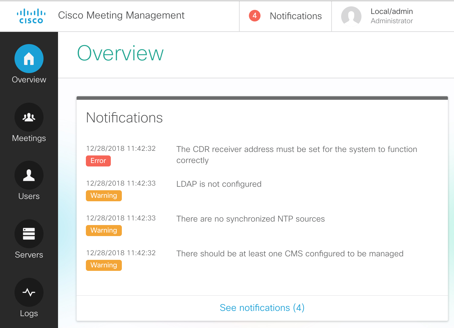
Let's complete the initial configuration by resolving these warning/error messages.
Add an NTP server
To configure the NTP server, perform the following
Add CDR Receiver
In order to receive information from Call Bridges, the CMM server needs to be installed as a CDR (Call Detail Record) receiver. The URL for this--which is usually just the URL of the CMM itself, https://cmm1.pod2.cms.lab in this example--is what the managed CMS servers will use to send CDRs to CMM. Therefore the CMM must be able to resolve this address via DNS and IP communication from CMS to port 443 (https) of the CMM must not be blocked. Furthermore, the certificate that CMM will present is configured here as well and it should be one that is signed by a private or public Certificate Authority, not the self-signed certificate that is installed by default.
Add CMS Servers
Next we will add our CMS servers.
Now you should see all 3 CMS servers properly added.
Add an LDAP server
Out of the box, Cisco Meeting Management creates only one local account, admin. While this may be sufficient for configuring the server initially, in most cases there is a group of users that will be allowed management of the conferences. This can be done by creating more local accounts, or we can utilize an LDAP group which will allow authorization based on LDAP group membership.
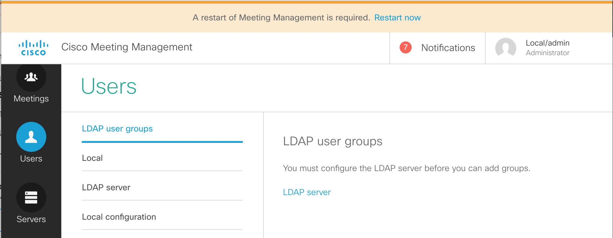
Add an LDAP user group
The restart only takes a minute or two. The LDAP configuration and our basic CMM configuration is now complete. Once the system has booted up again, let's sign in as the LDAP-synched video admin user and place a call into CMS.
This concludes the management portion of the lab. If you like, feel free to continue on and learn about client edge connectivity using Cisco Expressway. This will show you how to provide access for external WebRTC users. From there you can proceed to add support for external Skype for Business destinations via gateway calling.
You may also choose to skip ahead to the (shorter) Microsoft on-premise integration example, where you will learn about what is needed to configure a dual-home conferencing experience. From there you can pick up the Expressway Edge section, if time permits.
SECTION COMPLETE!
You've finished this portion of the lab. We have multiple other optional lab sections, depending on your time and interest, to continue on.
Troubleshooting
Quite often in the course of setting up or managing the CMS platform you may find the need to troubleshoot a particular problem either with configuration or day-to-day operational issues. Fortunately, there are several tools at your disposal to isolate issues if they occur. This section will walk you through a few of the tools at your disposal to isolate issues, as well as provide troubleshooting information to the Cisco TAC if required.
Tools
Below, you'll find a list of several of these tools that can be used to diagnose common problems.
Let's begin by taking a look at the various ways these different troubleshooting methods might be employed to gain visibility into what's going on with our CMS cluster in the event of an issue. We will look briefly at each method listed above, but be aware this will not be an exhaustive section. Each of these troubleshooting tools/methods can be used far beyond what we will take a look at in this lab. The goal of this section is to simply give you an idea of some of the ways to begin looking into common problems.
Webadmin
One of the first places to check when you suspect an issue with CMS is the Webadmin interface. Webadmin, when enabled, offers a quick glance at what the current state of the local node and cluster might be. You can check things like alarms as well as gather certain logs and enable detailed tracing. There are also some hidden areas that provide valuable information which we will look at.
System Status
Let's first take a look at the System Status on the General page to see if there are any glaring issues.
Detailed Tracing
Another way to take advantage of troubleshooting capabilities in the Webadmin interface is by enabling Detailed Tracing and viewing logs within the web browser. By enabling detailed tracing, you insure that the logs which are accessible in the browser (and in the downloadable syslog files) contain detailed trace information for troubleshooting purposes. Without enabling detailed tracing, the syslog messages logged will not contain more detailed troubleshooting information necessary to isolate certain issues.
Hidden Troubleshooting Pages
A little-known fact about CMS is a collection of hidden pages designed to provide certain information about individual CMS servers and the cluster as a whole. These pages are accessible once you've logged into the Webadmin interface, but are not linked-to from the standard menus at the top of the GUI. You won't find these pages documented officially and are not supported by Cisco TAC, but they can be useful for certain tasks that are only accessed via other methods such as the API. Our goal is simply to show you what tools are available and allow you to choose the right tool for a given task. With these caveats in mind, let's explore these hidden pages briefly.
Command Line Interface (CLI)
Syslog Follow
Depending what type of issue you're troubleshooting, there are some useful troubleshooting steps that can be performed via the CLI interface on each CMS server in your cluster. One of these steps is to issue the syslog follow command, which will provide a stream of syslog messages to the console and can be useful if the amount of syslog messages is somewhat small, or if you have a small cluster and need to isolate which node is handling a particular call, for instance.
Packet Captures
Another troubleshooting step that can be performed from the CLI is to start a packet capture that can then be downloaded via SFTP for analysis. This packet capture will show all packets entering or exiting a given interface on the CMS server. The packet capture is limited to 100MB.
|
psftp admin@cms1a.pod2.cms.lab
Using username "admin".
Using keyboard-interactive authentication.
Please enter password: c1sco123
Connected to cms1a.pod2.cms.lab.
Remote working directory is /
|
This is a very useful troubleshooting step that may even be requested by Cisco TAC under certain circumstances. For reproducible issues, you may be required by TAC to start a packet capture before reproducing a failed call, for instance. In the event that this is required, you can see that it's a fairly simple procedure.
SFTP
Directory Listing
A listing of all user-accessible files can be viewed by establishing an SFTP session to individual CMS nodes. These files include certificates and keys, license files, crash dump files, backup files, an audit log, pcaps.
|
psftp admin@cms1a.pod2.cms.lab
Using username "admin".
Using keyboard-interactive authentication.
Please enter password: c1sco123
Connected to cms1a.pod2.cms.lab.
Remote working directory is /
|
logbundle.tar.gz
Since version 2.2 of Meeting Server, the ability to collect logs via this single file has been available via SFTP. Included in this file is a copy of the CMS database, any .dmp files information on currently active calls, and syslog files. Note that the syslog file will only contain detailed logs if those logs have been enabled via the Webadmin interface (Logs --> Detailed Tracing). To collect this file, we will simply connect via SFTP to cms1a and issue the GET command.
|
psftp admin@cms1a.pod2.cms.lab
Using username "admin".
Using keyboard-interactive authentication.
Please enter password: c1sco123
Connected to cms1a.pod2.cms.lab.
Remote working directory is /
|
Once you have the archive, it can be extracted and its contents viewed. Shown below are the contents of the
logbundle:
This single archive is arguably one of the most important single troubleshooting files made available by CMS, and will often be requested by Cisco TAC engineers in their efforts to solve certain problems. Extracting the logbundle may be accomplished using 7Zip and various other utilities, but is beyond the scope of this lab. Awareness of this file, as well as what is contained within it is our focus today.
API
The API can be used for certain troubleshooting tasks as well. For instance, we can use it to query individual Callbridge nodes to see what their current load level is. We can also use it to obtain call diagnostic information or query the cluster to see what alarms are active, if any. For certain tasks, the API can be a very valuable troubleshooting tool.
For the scope of this lab, we will focus on one particular aspect of the API for troubleshooting purposes. It is possible to gather call diagnostic information using the API.
This concludes the troubleshooting section of the lab. Hopefully you have a better idea what tools are available to you as a CMS user, and can select the right tool for the job of troubleshooting any issues that may occur. While we would love to have a product that never has any issues, the reality is that there is always a need to understand and diagnose behavior that we don't understand in this or any product we may be using. Better understanding what tools are available to us can speed our time to resolution and provide a better overall user experience.