Configure Cisco Meeting Management
Cisco Meeting Management (CMM) is a product installed on a separate server that provides a user-friendly browser interface for video operators to monitor and manage meetings that are running on one or more Meeting Servers.
Install CMM
In this lab, we have already installed the CMM application for you. Since release 2.5, CMM allows both local and LDAP-synchronized accounts. Setting this up consisted of a few steps that we will point out here:
-
After deploying the provided virtual machine OVA of a size that conforms to the desired number of managed Call
Bridges and anticipated call volume, the server is booted up and host name, IP address, mask, default gateway,
and a DNS server are specified. The server then reboots and generates a self-signed certificate with a
local administrator account and password.
-
Accessing the CMM via the provided URL for the first time requires us to change the password. We have
done this step for you, so the credentials, as with other servers is admin /
c1sco123
At this point we can continue configuration of our system.
Post-Installation
This is where we pick up our installation. Your CMM's system administrators group includes the admin account. Let's log in now.
- Browse to https://cmm1.pod2.cms.lab
-
You'll get a certificate error, which you can accept, because we still only have a self-signed certificate on
this server. Then enter your credentials to sign in
(username: admin,
password: c1sco123)
- Press Sign in.
Once signed in, we see there are at least four notifications. LDAP and NTP are not yet configured.
Another warning indicates that there should be at least one CMS configured to be managed. Finally, the error states that a CDR receiver address must be set.
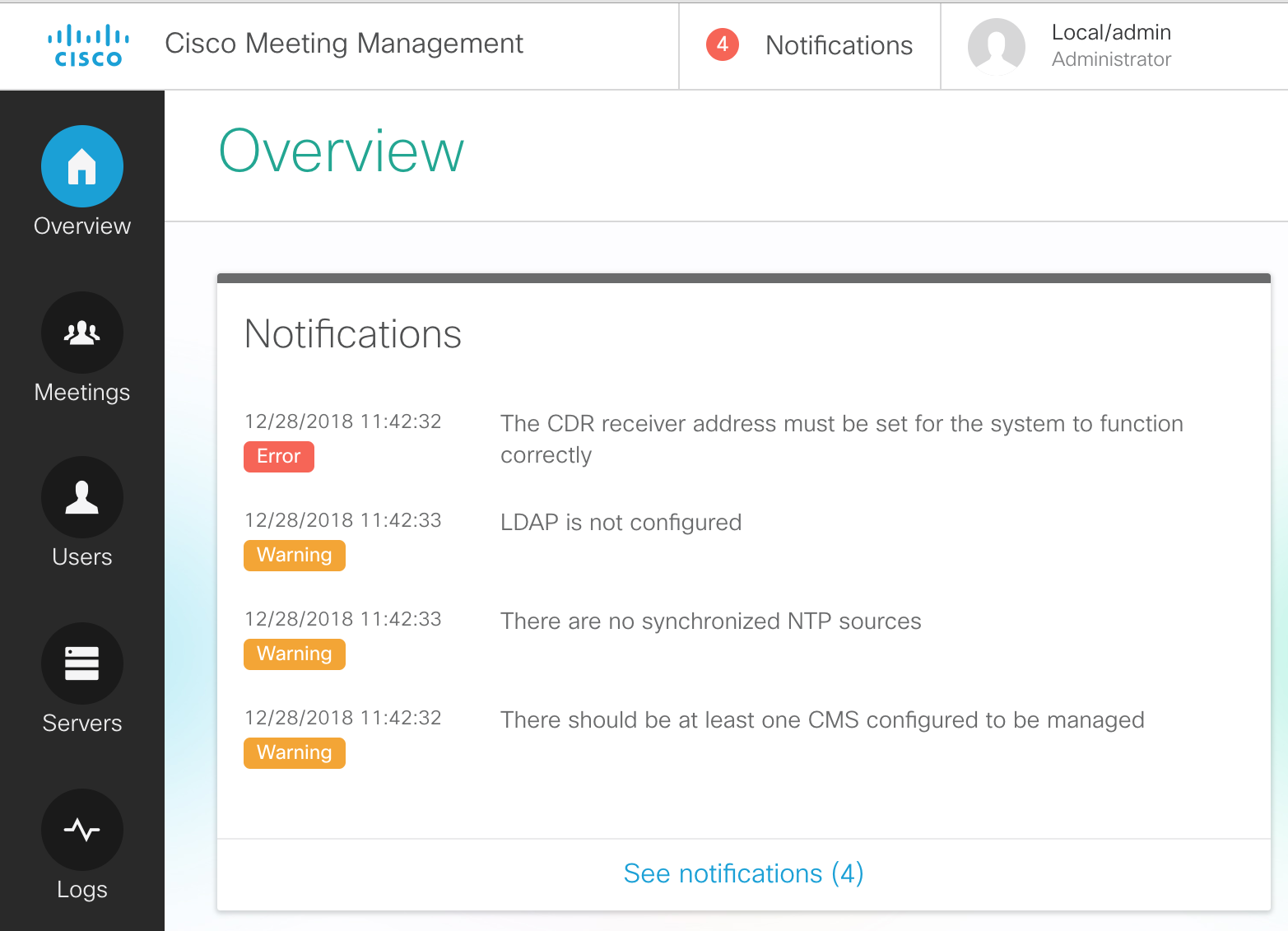
Let's complete the initial configuration by resolving these warning/error messages.
Add an NTP server
To configure the NTP server, perform the following
- On the left-hand side, click on the Settings button
- Click on NTP.
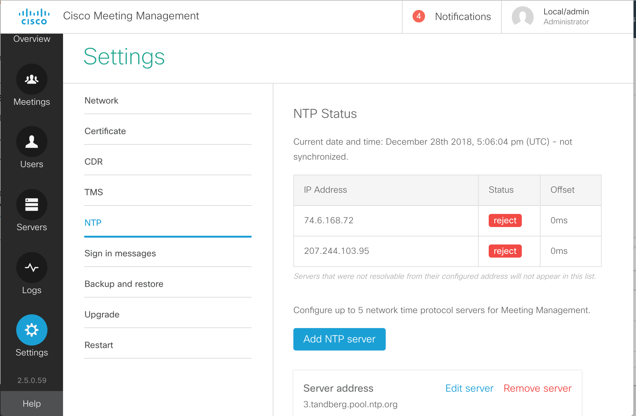
- You will see a few pre-configured NTP sources, which in most cases will not function. Let's first add our valid NTP source. Click Add NTP server.
- Enter 10.0.102.1
for the Server Address in the Add NTP server box.
- Click Add
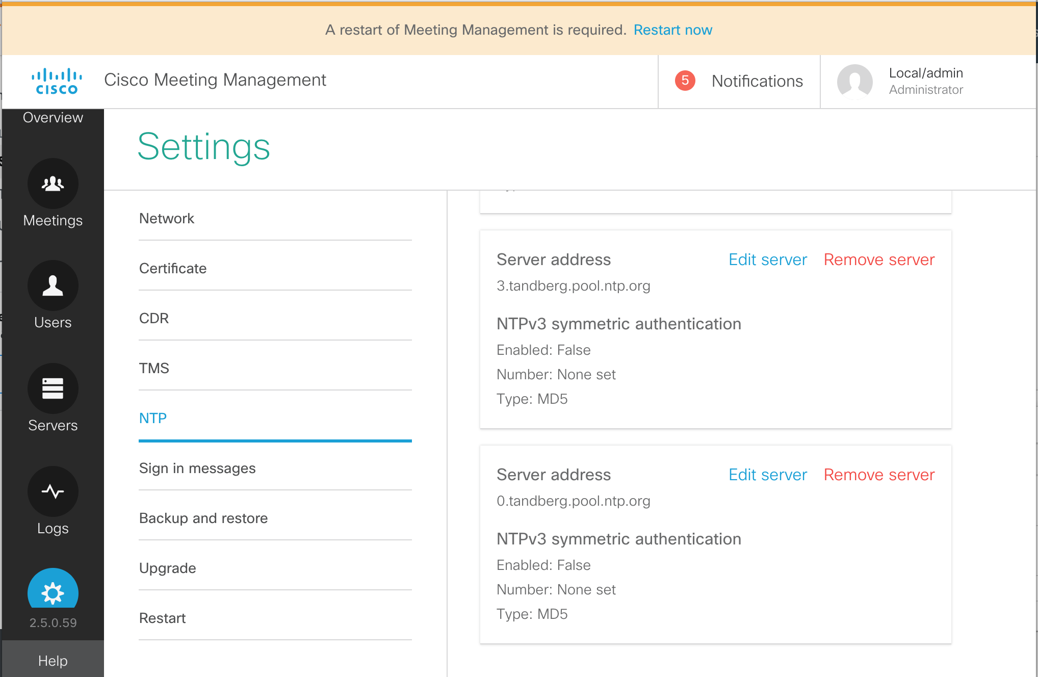
- You'll notice that CMM reports a message at the top of the page indicating that a restart of Meeting Management is required. We'll ignore this for now, as each of these server-level tasks will require a restart.
- To clean things up, let's remove the pre-configured NTP sources. They will all be
tandberg.pool.ntp.org. One at a time, click Remove server next to each.
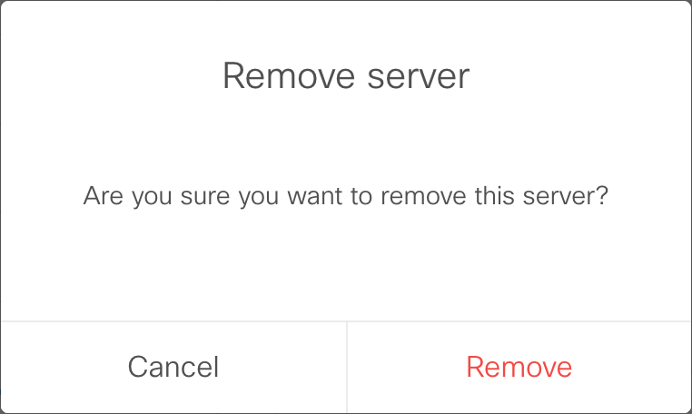
- Then confirm the tasks by clicking Remove in the confirmation box.
- Repeat this until only the single NTP server we configured, 10.0.102.1 is present.
Add CDR Receiver
In order to receive information from Call Bridges, the CMM server needs to be installed as a CDR (Call Detail Record) receiver. The URL for this--which is usually just the URL of the CMM itself, https://cmm1.pod2.cms.lab in this example--is what the managed CMS servers will use to send CDRs to CMM. Therefore the CMM must be able to resolve this address via DNS and IP communication from CMS to port 443 (https) of the CMM must not be blocked. Furthermore, the certificate that CMM will present is configured here as well and it should be one that is signed by a private or public Certificate Authority, not the self-signed certificate that is installed by default.
- While still in the Settings section, click CDR
- Click on the CDR line.
- For the CDR receiver address enter the address portion of our CMM URL:
cmm1.pod2.cms.lab
- Press Save
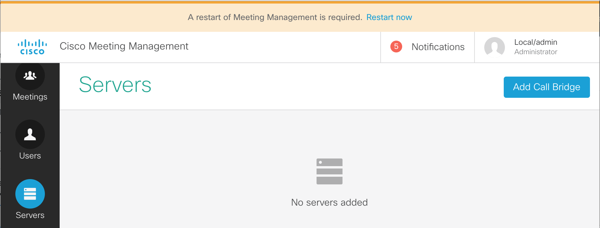
Add CMS Servers
Next we will add our CMS servers.
- Click on Servers from the buttons on the left.
- Click Add Call Bridge now on the right.
- Enter the information for cms1a. We do have DNS configured, so just enter cms1a.pod2.cms.lab in the Server address field.
- Enter the port for our web admin, 8443
- For the Display name field we can enter something that will make sense to the video conference operators. For example, let's enter POD2 CMS1a.
- Next we need to fill in the CMS API account credentials, apiadmin in the Username field and the Password, c1sco123 below it.
-
Finally, click the Add button.
-
You should now see a line with a Display name of Pod2 CMS1a.
The HTTPS column will show Unverified because
we are not using certificates that are trusted. We won't address that particular issue in this lab.
We do, however, need to add the other two Call Bridge servers that are part of our cluster
-
Below the added CMS server line you will see that it has 2 auto-discovered Call Bridges. Click the
show button to see cms1b.pod2.cms.lab and cms1c.pod2.cms.lab in the Server Address.
- Both CMS have the ? next to them instead of a check box next to the first column, meaning that they are not yet managed by CMM. To the right of cms1b.pod2.cms.lab server row (this may be the second or even the third row), in the Actions column, click the + button to add this Call Bridge.
- The Server address and Port are already pre-filled. To make things easier to identify, enter the Display name, POD2 CMS1b.
- The Username can be specified, apiadmin as well as the Password, c1sco123.
-
And press Add
- Once successfully, added, press the show button to see the last CMS, cms1c.pod2.cms.lab
- Press + at the right and we can enter the same information as before.
- For the Display Name, enter POD2 CMS1c.
- The enter the Username, apiadmin and Password, c1sco123
- Then the Add becomes active and you can click it.
Now you should see all 3 CMS servers properly added.
Add an LDAP server
Out of the box, Cisco Meeting Management creates only one local account, admin. While this may be sufficient for configuring the server initially, in most cases there is a group of users that will be allowed management of the conferences. This can be done by creating more local accounts, or we can utilize an LDAP group which will allow authorization based on LDAP group membership.
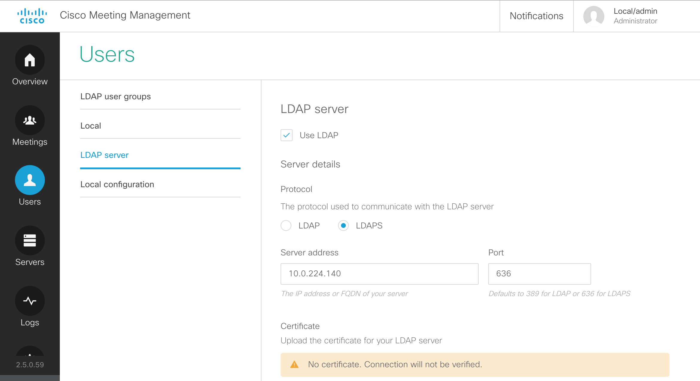
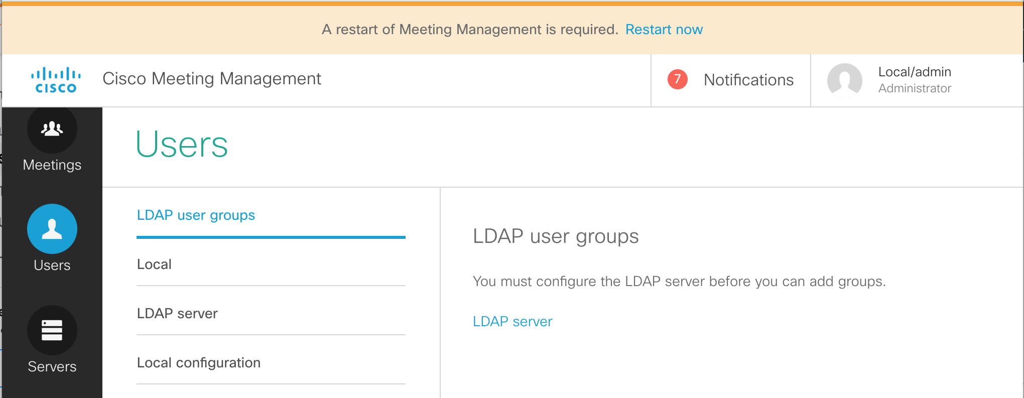
- From the CMM administration screen, select the Users button.
- We see that there are options for LDAP user groups. Local users are configured in the Local section. Local credential policies are configured under Local configuration. We're interested in configuring our LDAP source. Click LDAP server
- On this page, there are a number of settings to configured. First of all, check the Use LDAP checkbox.
- For the Protocol, choose LDAPS, for secure LDAP.
-
The Server address should be set to
10.0.224.140. The port
should be 636.
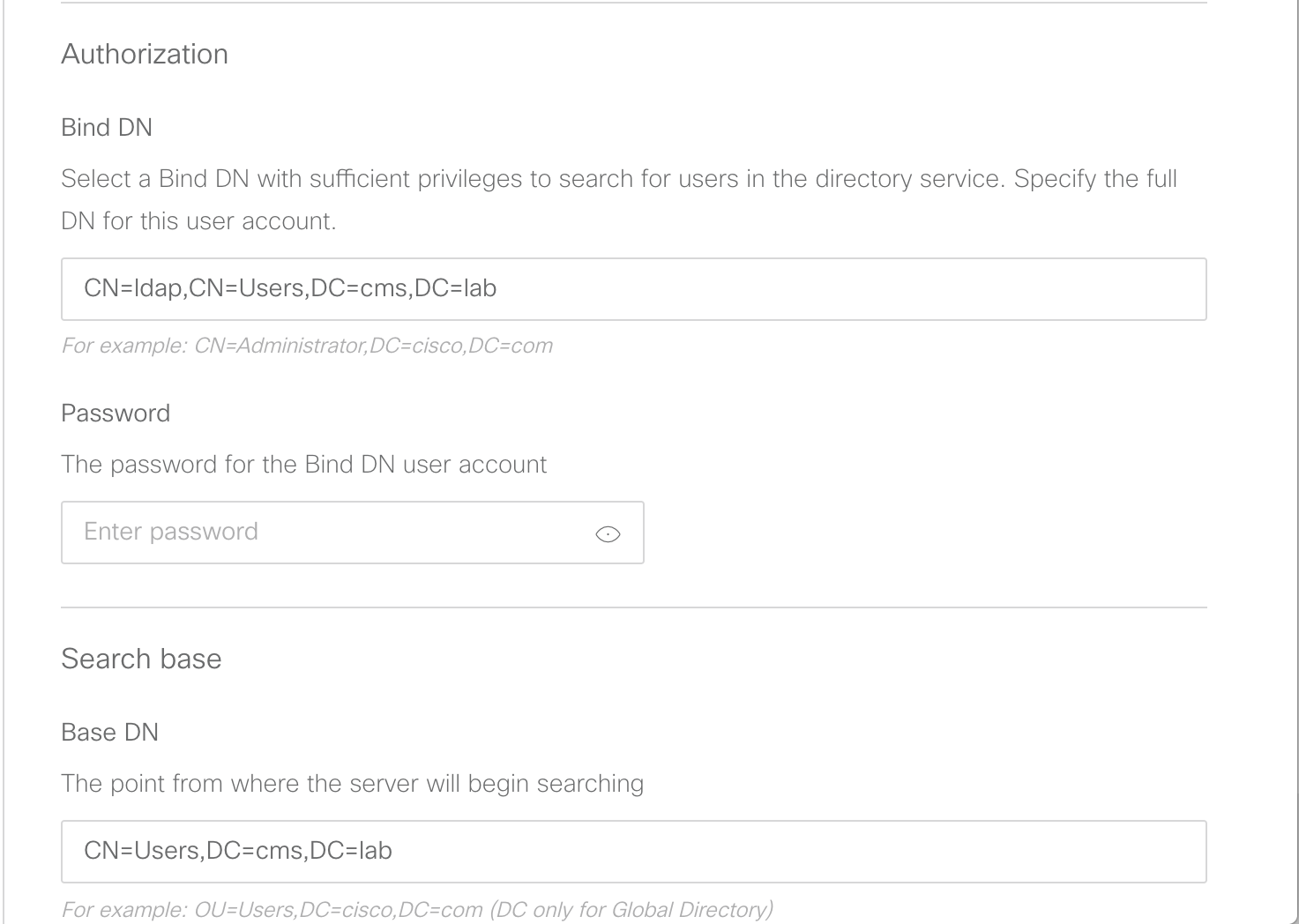
- We will keep the default certificate, but below in the Authorization section, configure CN=ldap,CN=Users,DC=cms,DC=lab
- Next, the Password for the Bind DN user account should be our usual c1sco123
-
The Base DN should be configured with:
CN=Users,DC=cms,DC=lab
-
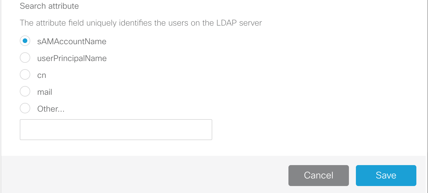
Leave the Search attribute set to sAMAccountName and click
Save
Add an LDAP user group
-
Navigate to the LDAP user groups section under the Users button.
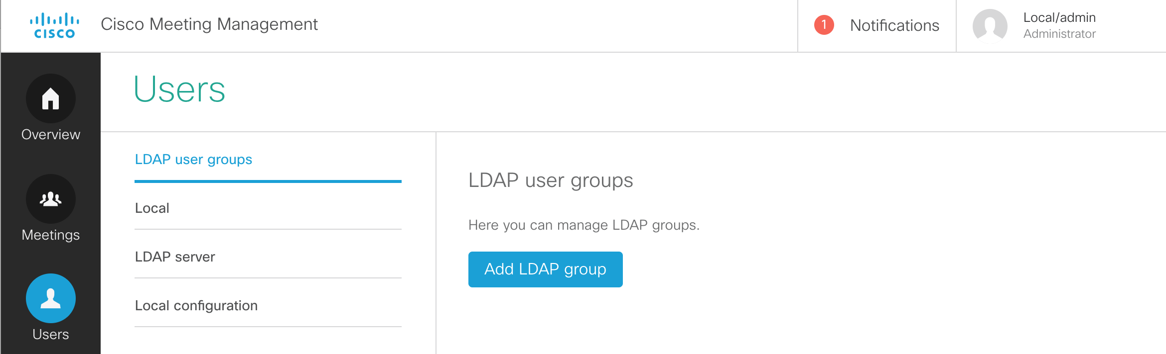
- You should now be able to click Add LDAP group.
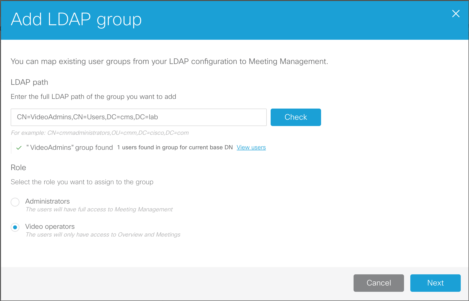
- We need to configure an LDAP path. Enter CN=VideoAdmins,CN=Users,DC=cms,DC=lab.
- Click the Check button. This allows us to not only make sure the group can be retrieved, but also allows us to view the group membership.
- We see that there is 1 user associated with that group. Click View users and you'll see that the account is vidadmin. There is nothing to do and anyone who would be added to that LDAP group would automatically be granted access to the CMM.
- Check the Video operators button so that we can add this group of Video operators.
- Click Next
- The URL that would be given to the video operators can be configured here. In our case, this is simply the URL of the CMM itself. Click Done.
- This change also requires a restart. We have had restarts pending since earlier, but now it's time for us to complete the installation. At the top of the screen, in the red banner, click Restart now, followed by Restart.
The restart only takes a minute or two. The LDAP configuration and our basic CMM configuration is now complete. Once the system has booted up again, let's sign in as the LDAP-synched video admin user and place a call into CMS.
- Browse to https://cmm1.pod2.cms.lab
- At the logon screen you'll notice that you now have a drop-down for LDAP and Local users. Select LDAP.
-
For the Username, enter our video admin user,
vidadmin
and password, c1sco123.
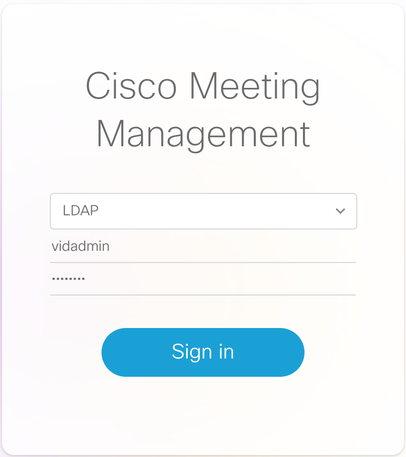
- Click Sign in
-
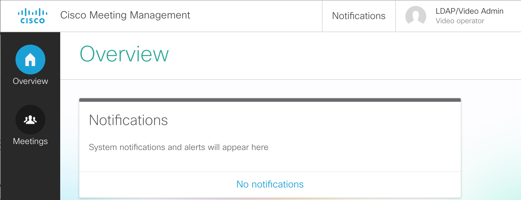
We see that we now only have the Overview and Meetings options and all the notifications have cleared.
- In the CMM GUI, click on the Meetings button. You see that there are currently no active meetings.
- From your laptop's Jabber client, dial your personal Space at pod2user1.space@conf.pod2.cms.lab
-
The meeting should show up automatically if Active now is selected.
Click on the active meeting, Pod2 User1's Space, under the meeting title.
-
You see all participants, and have buttons to change the layout, record (if configured), stream the
meeting (if configured), and add participants. Let's add someone. Click the + button
under Add participants.
- For the participant's address to add, enter pod2user1@pod2.cms.lab and press Enter
- Then enter another participant, pod2user2@pod2.cms.lab and press Enter
- Click Add.
-
Both particpants are added. This may cause some feedback, but with CMM we can hover over each of the
participants and easily click the mute button.
-
If we click on our local user, the line with Pod2 User1, we can change that
participant's layout and see information about the call. You'll notice that we can see the display name
of the CMS that we configured previously, so you can tell which CMS this meeting is hosted on.
- When we're finished, click the End Meeting
This concludes the management portion of the lab. If you like, feel free to continue on and learn about client edge connectivity using Cisco Expressway. This will show you how to provide access for external WebRTC users. From there you can proceed to add support for external Skype for Business destinations via gateway calling.
You may also choose to skip ahead to the (shorter) Microsoft on-premise integration example, where you will learn about what is needed to configure a dual-home conferencing experience. From there you can pick up the Expressway Edge section, if time permits.
SECTION COMPLETE!
You've finished this portion of the lab. We have multiple other optional lab sections, depending on your time and interest, to continue on.
-
Understand other CMS features, such as:
- Spaces, to understand more about how Spaces are organized and configured.
- Ad-hoc conferencing and integration with the Unified CM
- CallBridge Groups for load balancing calls
- Branding, for a more customized deployment.
-
Explore Cisco Single Edge with Cisco Expressway and CMS:
- Learn about deploying external WebRTC Web App using Cisco Expressway, to provide external users the same Web Bridge capability.
- Configure advanced Business-to-business calling with Skype for Business gateway calling.
- Investigate a Microsoft on-premise integration example, where you will learn about what is needed to configure a dual-home conferencing experience.